


 |
128X48 Graphic COG LCD ST7565R-G | STN+ Display with White Side Backlight/HTG12848A
Product Details:
| Place of Origin: | Dongguan, China |
| Brand Name: | HOTHMI |
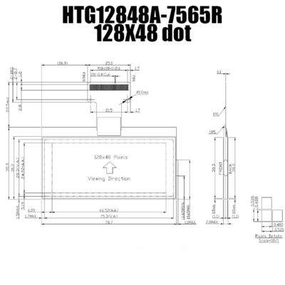
| Model Number: | HTG12848A-7565R |
Payment & Shipping Terms:
| Minimum Order Quantity: | 2 |
|---|---|
| Delivery Time: | 25 days |
| Payment Terms: | L/C, D/A, T/T, D/P, Western Union, MoneyGram |
|
Detail Information |
|||
| Product Type: | COG | Show Contents: | 128x48 |
|---|---|---|---|
| Outline Size(mm): | 81.1x38.3x4.9 | Size Of View Window(mm): | 75.3x28.3 |
| Display Size(mm): | 66.52x24.92 | Point Spacing(mm): | 0.52x0.52 |
| Visual Angle: | 6H | Connection PIN Number: | FPC-28PIN |
| Interface Mode: | MCU/8bit | Working Temperature: | -20~70℃ |
| Power Supply Voltage: | 3.3v | Driver Chip Model: | ST7565R |
Product Description
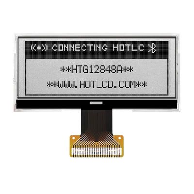
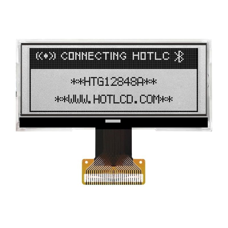
128X48 Graphic COG LCD ST7565R-G | STN Gray Display With WHITE Backlight/HTG12848A
128X48 Graphic COG LCD ST7565R-G | STN+ Display with White Side Backlight/HTG12848A
HOTLCD 128x48 graphic Chip-On-Glass (COG) Liquid Crystal Display shows dark pixels on a white background. This transflective LCD Display is visible with ambient light or a backlight while offering a wide operating temperature range from -20 to 70 degrees Celsius. This HTG12848A display has an optimal view of 6:00, operates at 3.3V supply voltage and is RoHS compliant. This display comes with a built-in ST7565R-G controller.
Product parameters
| ITEM | STANDARD VALUE | UNIT |
| Number of dots | 128x48 DOTS | ---- |
| Module dimension | 81.1x38.3x4.9 | mm |
| View display area | 66.52x24.92 | mm |
| Dot size | 0.48x0.48 | mm |
| Dot pitch | 0.52x0.52 | mm |
| Operating temp | -20~70 | ℃ |
| Storage temp | -30~80 | ℃ |
| Driving Method | 1/ 128 DUTY,1/ 12 BIAS,VOP= 3.3V | |
| Viewing direction | 6 O’CLOCK | |
| Display mode | STN | |
| Display type | TRANSMISSIVE / NEGATIVE | |
| Driver IC | ST7565R | |
| Backlight |
WHITE |
|
Pin_SIGNAL
| Pin No. | Pin Name | Function |
| 1 | VDD | Power supply |
|
2 |
P/S |
This pin configures the interface to be parallel mode or serial mode. P/S = “H”: Parallel data input/output. P/S = “L”: Serial data input. |
|
3 |
C86 |
This is the MPU interface selection pin. C86 = “H”: 6800 Series MPU interface. C86 = “L”: 8080 Series MPU interface. |
|
4~8 |
V5~V1 |
This is a multi-level power supply for the liquid crystal drive. The voltage Supply applied is determined by the liquid crystal cell, and is changed through the use of a resistive voltage divided or through changing the impedance using an op. amp. Voltage levels are determined based on Vss, and must maintain the relative magnitudes shown below. V1 ≧V2 ≧V3 ≧V4 ≧V5 |
| 9 | C2+ |
When internal DC-DC voltage converter is used, external capacitor is connected between these pins. |
| 10 | C2- | |
| 11 | C1+ | |
| 12 | C1- | |
| 13 | C3+ | |
| 14 | VOUT | Positive voltage supply pin of the chip. |
| 15 | VSS | Negative power supply,0V |
| 16~23 | D7~D0 |
8bit Date bus, D7 : serial data input (SI) ; D6 : the serial clock input (SCL) |
|
24 |
E |
• When connected to 8080 series MPU, this pin is treated as the “/RD” signal of the 8080 MPU and is LOW-active. The data bus is in an output status when this signal is “L”. • When connected to 6800 series MPU, this pin is treated as the “E” signal of the 6800 MPU and is HIGH-active. This is the enable clock input terminal of the 6800 Series MPU. |
| 25 | R/W | When R/W = “H”: Read. When R/W = “L”: Write. |
|
26 |
A0 |
This is connect to the least significant bit of the normal MPU address bus, and it determines whether the data bits are data or command. A0 = “H”:Indicates that D0 to D7 are display data. A0 = “L”: Indicates that D0 to D7 are control data |
| 27 | /RES | Reset |
| 28 | /CS1 |
Chip selection input |
Search Keyword: lcd 128x48, lcd 128 x 48, 128x48 lcd, 128 x 48 lcd