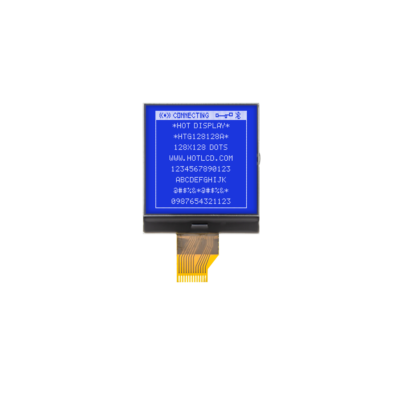
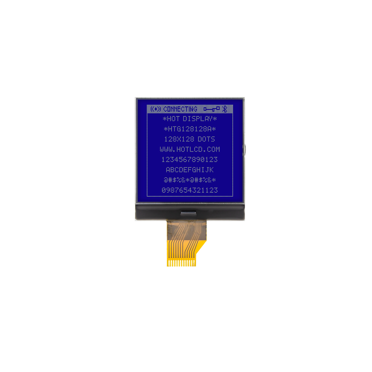
128×128 COG LCD Display STN-Negative With White Backlight
- Model: HTG128128A-25W
- Type: COG graphic lattice
- Display pixels: 128×128
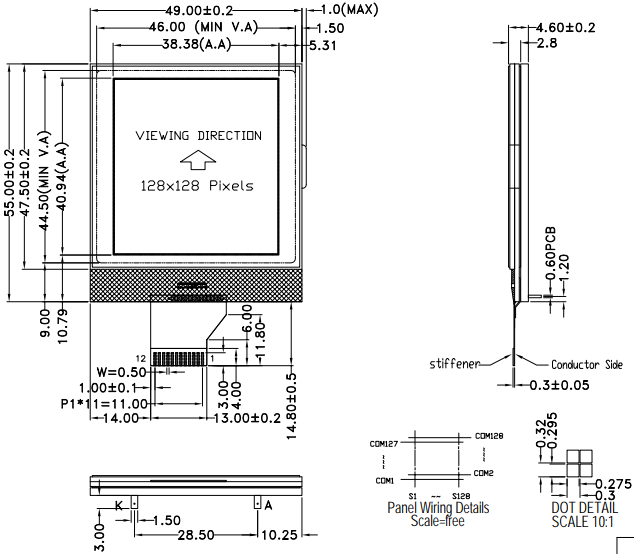
- Overall dimensions (mm): 55.0×49.0x4.6
- VA size (mm): 46.0×44.5
- Working temperature: -20~70℃
- Supply voltage: 3.0V
- Driver chip: UC1617S
Original price was: $20.00.$16.00Current price is: $16.00.
(Save $4.00)
In stock
Description
Features of the 128×128 COG LCD Display
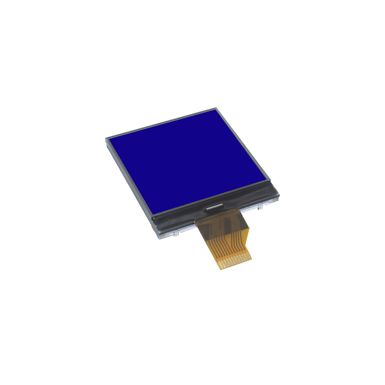
The HTG128128A-25W 128×128 COG LCD display, with its excellent overall performance and unique display effects, is an ideal choice for various precision instruments and meters. This module utilizes advanced Chip-On-Glass (COG) technology, integrating the UC1617S driver chip directly onto the glass substrate. This highly simplified structure results in an ultra-thin body of only 4.6 millimeters, significantly improving mechanical stability and reliability.
Its display is clear and visually appealing, featuring a high-contrast design with a blue background and white patterns, ensuring strong visual recognition. In terms of performance, the 128×128 COG LCD display, thanks to its SPI interface and efficient chip design, can be driven with a low voltage of only 3.0V, resulting in extremely low power consumption. Furthermore, it boasts a wide operating temperature range of -20~70℃ and 8KV electrostatic discharge protection, ensuring superior adaptability and long-term operational stability in demanding industrial environments.
This 128×128 COG LCD display perfectly combines a lightweight and thin structure, low power consumption, high stability, and high-quality blue and white display, making it a tailor-made display solution for devices requiring compactness, reliability, and a clear human-machine interface.
The structural components of a 128×128 COG LCD display
A complete 128×128 COG LCD display module is a sophisticated laminated system, primarily consisting of the following layers from inside to out:
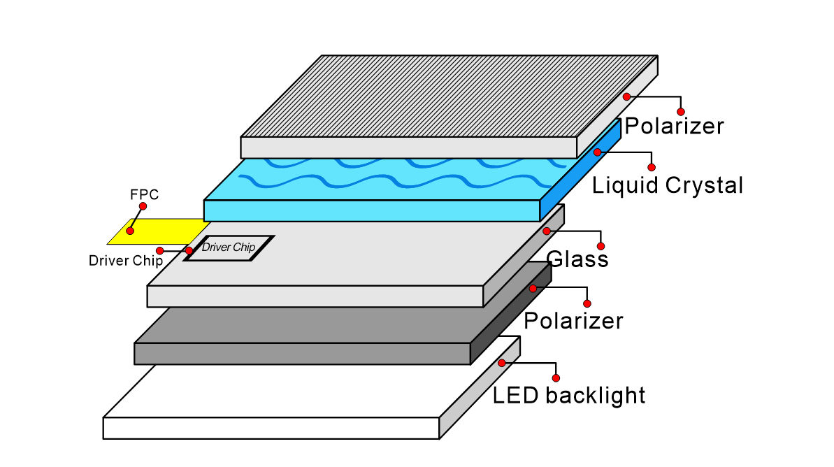
Lower Glass Substrate:
As the main body, its inner surface has 128 x 128 transparent ITO (Indium Tin Oxide) electrodes etched using photolithography, forming a pixel matrix. We directly bond the COG driver chip (UC1617S) to the edge pads of this glass substrate.
Liquid Crystal Layer:
Filled between the upper and lower substrates, its orientation is controlled by an electric field to change light transmittance.
Upper Glass Substrate (Counter Substrate):
The inner surface has a common ITO electrode, which, together with the lower pixel electrodes, forms the electric field that controls the liquid crystal.
Polarizers:
A polarizer is attached to the outer side of both the upper and lower glass substrates, with their polarization directions perpendicular to each other (usually 90 degrees). This is key to achieving the blue background and white text effect: the liquid crystal modulates the light, presenting a blue background in the unpowered (default) state, and the pixel area turns white when powered.
Backlight Unit:
Located below the entire display layer, it consists of white LED beads, a light guide plate, and a reflective film, providing a uniform white background light for the display. The lower polarizer, liquid crystal layer, and upper polarizer together modulate the light to produce a high‑contrast blue‑and‑white display.
Connection and Support:
FPC (Flexible Printed Circuit) – 12PIN: Connected to the pins on the glass substrate through a hot-pressing process, it introduces the SPI signals, power, and ground from the external main controller to the UC1617S chip.
Module Frame and Protection:
Usually a metal or plastic frame, used to fix and protect all internal components and provide mounting holes. The surface may be covered with a protective film or a touch panel.
In summary, the 128×128 COG LCD display is essentially a miniature optoelectronic system that integrates the driver chip, precision electrodes, liquid crystal material, optical films, and backlight system using COG bonding technology. This structure allows it to achieve stable, clear, and energy-efficient graphic display functions within a small space.
The core manufacturing process of the COG LCD display
COG technology is the key technology for this 128×128 COG LCD display. Unlike traditional LCDs, which solder the driver chip (IC) onto a separate PCB board, COG technology directly and precisely bonds the dedicated bare-die driver chip (such as the UC1617S in this example) to the edge pins of the glass substrate using conductive adhesive (ACP).
Technological Advantages:
Ultra-thin and Lightweight: By eliminating the need for separate IC packaging and the PCB space required for soldering, the total thickness of this 128×128 COG LCD display is significantly reduced (4.6mm), resulting in an exceptionally compact structure.
High Reliability: Direct bonding reduces the number of connection points and instability between the chip and the glass, providing strong resistance to vibration and impact, and ensuring a more stable connection.
Low Power Consumption and High Performance: The shortest possible distance between the chip and the display electrodes minimizes signal transmission loss and maximizes speed, facilitating low-voltage (3.0V) driving and fast display response.
Application scenarios for 128×128 COG LCD
The 128×128 COG LCD display, with its compact structure, low power consumption, high stability, and distinct blue-and-white high-contrast display, perfectly suits professional and industrial fields with stringent requirements for reliability, space, and energy efficiency.
Industrial Control and Instrumentation:
The 128×128 COG LCD display’s wide operating temperature range (-20~70℃) and strong anti-static capabilities (ESD 8KV) ensure stable operation in factory environments with complex electromagnetic conditions and large temperature variations. It is suitable for portable testing equipment, sensor reading panels, calibrators, and process control displays.
Medical and Healthcare Equipment:
The thin and lightweight characteristics of the COG process facilitate device miniaturization; low power consumption (3.0V drive) significantly extends the battery life of battery-powered devices. This makes the 128×128 COG LCD display suitable for handheld monitors, portable diagnostic equipment, infusion pump panels, and rehabilitation equipment human-machine interfaces.
Automotive Applications:
Excellent stability allows it to withstand vibrations and wide temperature variations during vehicle operation; the clear blue-and-white display conforms to the visual habits of in-car information displays, facilitating quick identification. Suitable for tire pressure monitoring system (TPMS) display terminals, in-car air conditioning/audio auxiliary displays, and OBD diagnostic devices.
We designed the 128×128 COG LCD display not for consumer entertainment applications that prioritize vibrant colors, but to provide a clear, reliable, and durable human-machine interface for professional tools and critical equipment. It is the preferred solution for engineers in any scenario where information needs to be consistently clear and visible in limited space and power conditions.
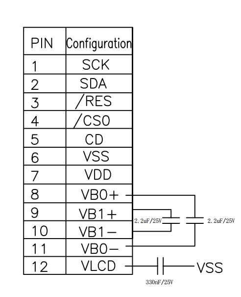
12-pin COG LCD display wiring diagram reference:
What customization options can we offer for this COG LCD display?
| Connector customization: Easily modify any connector on the display to meet your application requirements. Our engineers can solder pin headers, box headers, right-angle connectors, and any other connectors your display may require. |
| PCB modification: Choose from a variety of changes to the PCB shape, size, pinout, and component layout to perfectly fit your application. |
| Backlight color customization: The module backlight has a variety of combinations to choose from, including no backlight or yellow-green/blue/white/amber/red/RGB backlight options, with up to 48 effects to choose from. Click on the customization page for reference. |
| Font Customization: A variety of font libraries are available, including English/Japanese, Western European, Eastern European, Scandinavian European, Cyrillic (Russian), Hebrew/Arabic, and more. |
| Cable Customization: Adjust cable length, position, and pinout, or add additional connectors. Get a precisely designed cable solution that streamlines and secures your connections. |
FAQ about 128×128 COG LCD display
Q1:Do I need to write the low-level driver for the UC1617S chip myself when developing with this 128×128 COG LCD display?
A: Usually, yes. We will provide basic initialization code examples and timing references, but the complete graphics library (such as drawing points, lines, characters, and images) often requires the developer to port or write it themselves based on the SPI communication protocol.
Q2:This 128×128 COG LCD display has an operating temperature range of -20~70℃. Can it operate at even lower or higher temperatures?
A: The operating temperature range of -20~70℃ is the range within which its normal operation is guaranteed. Operating outside this range may lead to slower response times, reduced contrast, or even complete failure. However, we can modify the display through processing to achieve a wider operating temperature range, such as -30~80℃.
Q3:What are the backlight uniformity and lifespan of this 128×128 COG LCD display?
A: Using a side-lit LED + light guide plate design, the brightness uniformity between the center and edges meets industrial standards under reasonable driving current (typically 15-20mA). The LED backlight lifespan is typically 30,000 to 50,000 hours (the time it takes for the brightness to decay to 50% of its initial value).
Attributes
| PARAMETER | SPECIFICATION CONTENT | UNIT |
| Name | HTG128128A-25W | |
| Graphic Display | 128 x 128 | dots |
| Dimensions | 55.0(W) × 49.0 (H) × 4.6 (T) | mm |
| VA Size | 46.0 x 44.5 | mm |
| AA Size | 40.935(W) × 38.375(H) | mm |
| Pixel Pitch | 0.295(W) × 0.275(H)mm | mm |
| Driver Chip | UC1617S | |
| Applied Voltage | 3.0V | V |
| Backlight Illumination | White | |
| Display Mode | STN(-) | |
| Drive Mode | 1/128 duty cycle | |
| Product Type | Graphic LCD | |
| Polarizer Type | Transmissive |
Related products