
Description
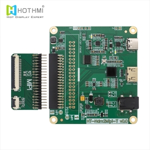
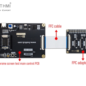
High Performance Industrial Display Board: Professional SPI/MCU to TTL Signal Conversion Module
In the rapidly evolving landscape of embedded systems and human machine interface design, the need for seamless signal conversion is paramount. HOTHMI introduces a sophisticated solution for engineers: the SPI/MCU to TTL signal conversion module. This industrial display board serves as a powerful bridge, allowing standard serial or parallel microcontrollers to drive high resolution RGB interface TFT displays with minimal processing overhead.
Key Features and Technical Highlights
This industrial display board is engineered to offload complex graphical tasks from the host processor, providing integrated features that enhance both performance and visual quality.
- Multi Interface Compatibility and High Resolution Support
The board supports both SPI serial ports and 8/16 bit MCU parallel interfaces. It is capable of driving 16 bit (5/6/5) or 24 bit (8/8/8) RGB interface TFT displays. With support for resolutions up to 1024 by 768, it ensures crisp and clear imagery for a wide variety of panel sizes. - Integrated 128Mb Display Memory
Equipped with high capacity built in 128Mb display memory, the module supports multiple display buffers. This allows for seamless switching of the main display window and supports Alpha RGB 8:8:8:8 color depth, providing rich and vibrant visual transitions. - Hardware Level Graphic Acceleration
The board features a built in 2D BitBLT graphics acceleration engine. This enables high speed image copying with ROP raster operations, Picture in Picture (PIP) functionality, and transparent graphics blending. Additionally, an integrated geometric drawing engine allows the hardware to render points, lines, curves, ellipses, triangles, and rectangles directly, saving significant MCU clock cycles. - Built in JPG Hardware Decoder
To facilitate faster image loading and reduce memory bandwidth usage, the industrial display board includes a dedicated JPG hardware decoder. This allows for efficient decompression and display of image files, making it ideal for GUI intensive applications. - Rugged Industrial Grade Specifications
Designed for stability in harsh environments, the module operates within a wide temperature range of -40 degrees Celsius to +85 degrees Celsius. It requires a stable power supply voltage of 3.0V plus or minus 0.3V.

Industrial Applications of the Display Board
The versatility and robustness of this industrial display board make it suitable for various professional sectors:
- Industrial Automation: Used in PLC display terminals, factory monitoring systems, and sophisticated industrial instrument panels where reliability is non negotiable.
- Medical Equipment: Ideal for patient monitors, diagnostic imaging displays, and handheld medical analytical tools that require high color accuracy.
- Energy and Power: Integration into EV charging stations, smart grid monitoring terminals, and solar inverter control panels.
- Smart Security and Building Systems: Powering video intercoms, elevator multimedia displays, and smart building management interfaces.
- Automotive and Transportation: Supporting secondary information displays and multimedia systems in transit vehicles.
Technical FAQ: Implementing the Industrial Display Board
The following technical questions address common integration challenges faced by developers when using this signal conversion module.
Q: How does the industrial display board communicate its busy status to the host MCU?
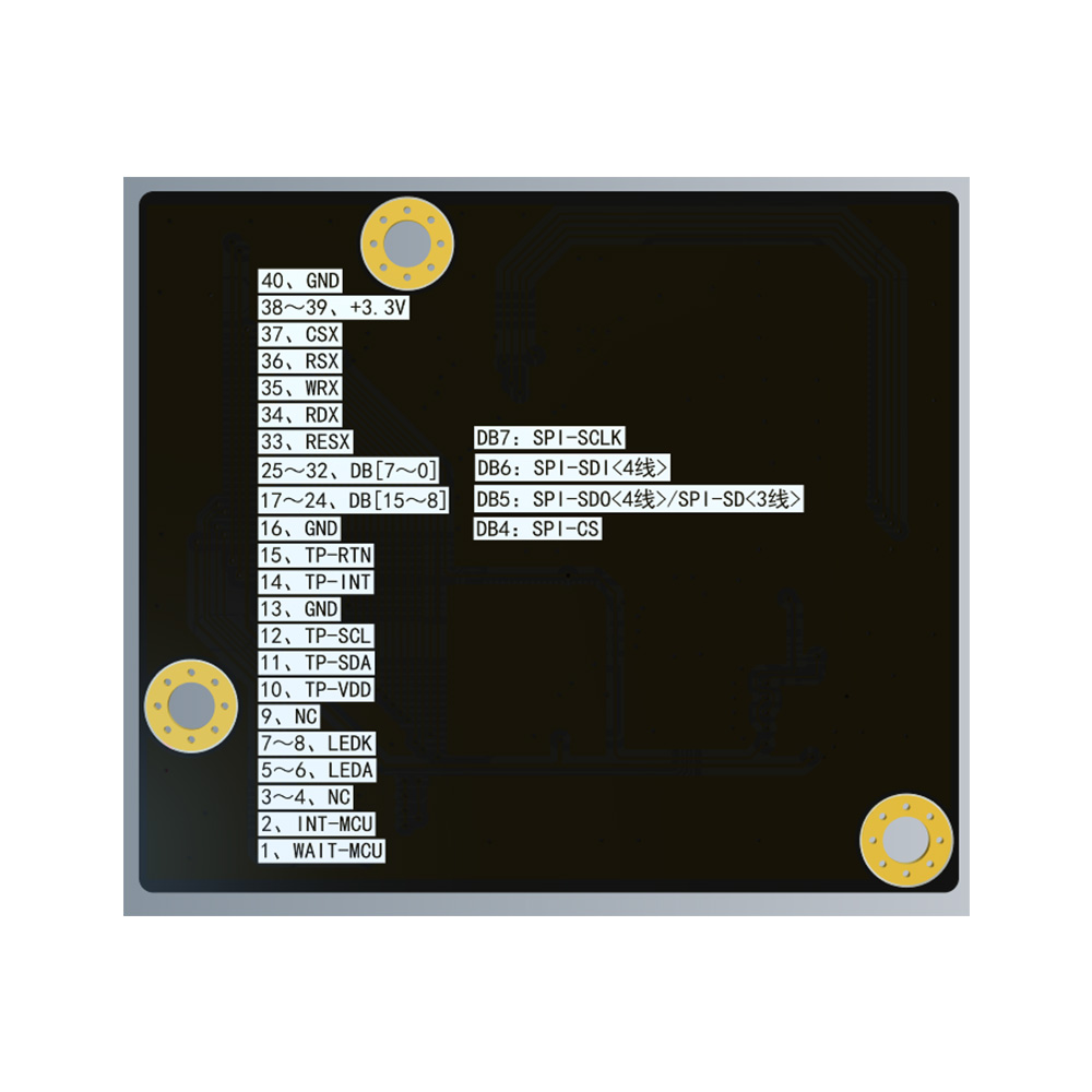
A: The module features a dedicated WAIT output signal on Pin 1. When the MCU performs read or write operations, if the module is internally busy, the WAIT signal will pull to a low potential. This informs the MCU to enter a waiting period, ensuring data integrity and preventing communication collisions.
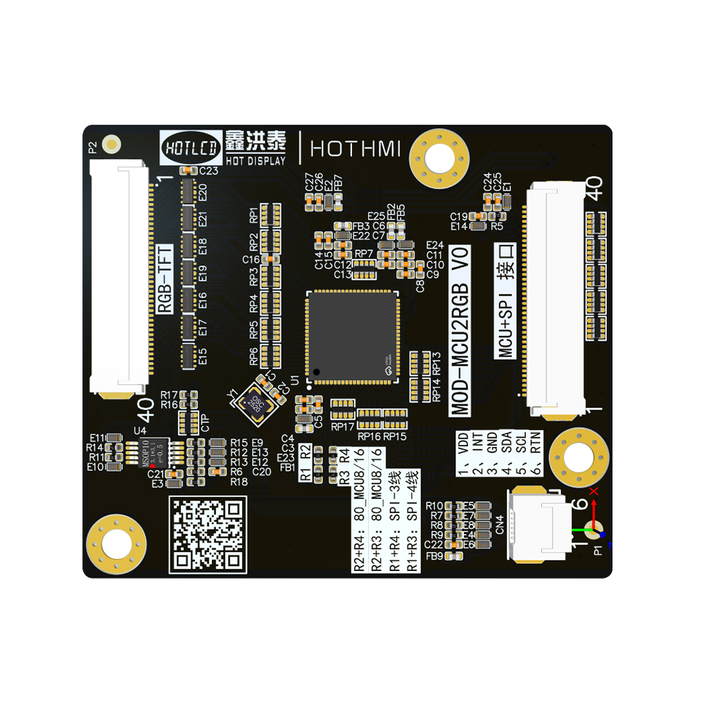
Q: What are the pin configurations for the SPI interface mode?
A: In SPI mode, several data bus pins are repurposed for serial communication. Pin 25 (DB7) acts as the SPI SCLK (clock). Pin 26 (DB6) serves as the SPI SDI (data input) in 4 wire mode. Pin 27 (DB5) functions as the SPI SDO (data output) in 4 wire mode or as a bidirectional data pin in 3 wire mode. Pin 28 (DB4) is used for SPI CSX (chip select).
Q: Can this board drive both 16 bit and 24 bit RGB panels?
A: Yes, it is highly flexible. The board can drive 16 bit (565) or 24 bit (888) RGB interfaces. Users can configure the output via the RGB interface pins, which include 8 bits each for Red (DR0 to DR7), Green (DG0 to DG7), and Blue (DB0 to DB7).
Q: What precautions should be taken to prevent screen burn in or image retention?
A: For normally black panels, it is strongly recommended not to display fixed patterns for extended periods. If a fixed image is necessary, the content should be refreshed at least once every two minutes. Implementing a screen saver with moving images or a black background is highly advised for long term display health.
Q: Is there support for capacitive touch panel (CTP) integration?
A: Absolutely. The industrial display board provides dedicated CTP interface pins, including TP VDD, TP INT, TP SDA, TP SCL, and TP RTN. These pins facilitate I2C communication between the touch controller and the main system, allowing for interactive user interfaces.
-300x300.jpg)