A Comprehensive Analysis of RGB Interfaces in TFT-LCD Displays
Connecting MCUs, MPUs, or CPUs to LCD displays can be achieved through various interface options. These solutions differ in the number of signal lines, data transfer rate, power consumption, and suitable application scenarios. The RGB interface is one of the important methods.
Basic Concepts of Display Driving
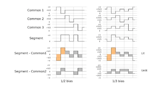
Before understanding the RGB interface, it is necessary to clarify the fundamental driving requirements of liquid crystal displays. LCDs cannot be driven by DC voltage; they must use AC voltage, and the total current flowing through the liquid crystal material must be zero. If a DC component persists over time, the liquid crystal material will gradually degrade.
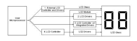
In terms of drive architecture, modern TFT-LCD panels are primarily driven by the collaborative work of Gate Drivers (responsible for row scanning) and Source Drivers (responsible for column data input).
Traditional MCU interface displays typically have a built-in controller and Graphic RAM (GRAM). The microprocessor simply writes pixel data to this GRAM. In contrast, the RGB interface is different—the display end usually does not have its own GRAM. Instead, it requires the external host chip’s LCD controller to continuously and in real-time output clock and pixel signals to maintain the displayed image.
Basic Concept of the RGB Interface
The RGB interface is a data transmission interface between the display and the image processor. The letters R, G, and B stand for Red, Green, and Blue—the three primary colors that form the basis of color imaging in display devices. The core function of the RGB interface is to directly transmit the computed color information for each pixel from the image processor to the display’s driving circuitry.
In display technology, each pixel consists of three sub-pixels (Red, Green, and Blue). By adjusting the brightness levels of these three sub-pixels, a wide variety of colors can be produced. For example, all three at maximum brightness produce white, all off produce black, and mixing red and green produces yellow. The data transmitted via the RGB interface is, therefore, the specific brightness value for each sub-pixel.
Characteristics of the RGB Interface
Advantages:
- High transmission efficiency—data does not need to be packed or unpacked, resulting in low latency.
- Simple signal timing, making driver design and debugging relatively straightforward.
- Well-suited for small-size, low-resolution display applications.
Disadvantages:
- Requires a large number of signal lines, consuming significant PCB routing space and connector pins.
- Limited transmission distance; signal quality degrades over longer cables.
- Risk of electromagnetic interference (EMI) between parallel signal lines, requiring careful attention to shielding and trace spacing during design.
- As resolution increases, the number of required data lines or the transmission frequency must rise significantly, leading to increased power consumption and routing complexity.
Current Applications of the RGB Interface in Modern Devices
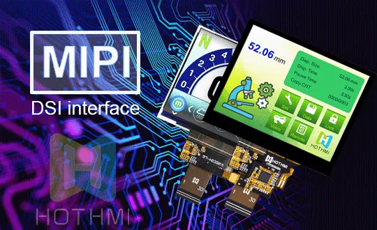
In early LCDs and small-to-medium-sized screens, the original parallel RGB interface was the mainstream solution. However, as display resolutions have evolved from VGA (640×480) towards Full HD and 4K, the limitations of the parallel interface have become increasingly apparent. Modern smartphone, tablet, and laptop screens no longer use the original parallel RGB interface, instead adopting serialized interfaces like LVDS, eDP, or MIPI DSI.
Nevertheless, these newer interfaces have not abandoned the RGB color representation method. They still transmit Red, Green, and Blue color data, but they use techniques like serialization and packetization to compress the original parallel data onto fewer signal lines, thereby meeting the design demands of higher resolutions, lower power consumption, and narrower bezels.