LCD and CTP Interface Overview – UART Interface
Multiple connection methods exist between an MCU (Microcontroller Unit), MPU (Microprocessor Unit), or CPU (Central Processing Unit) and an LCD display, with the UART interface being one such option.
Fundamental Concept (1): LCD Driving Waveform
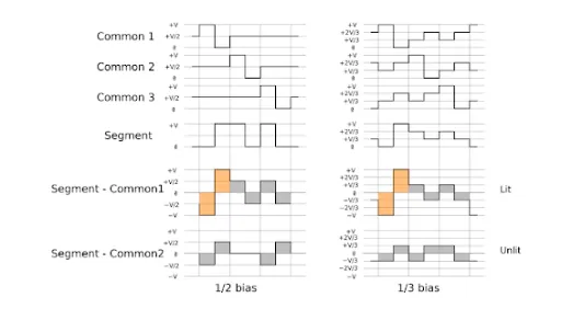
LCD panels cannot be driven by direct current (DC); they require alternating current (AC) for proper operation, and the net current must be zero over time. If this condition is not met, the liquid crystal material will inevitably degrade and become damaged.
Fundamental Concept (2): LCD Controller vs. Driver
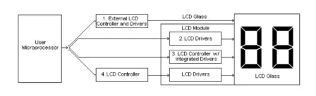
Driver ICs fall into two main categories: common drivers and segment drivers. Common drivers generate signals that define the rows or the number of scanning lines, while segment drivers produce the signals needed to form characters or columns.
The controller IC accepts data from the MPU in ASCII or JIS code formats and temporarily stores it in its internal RAM. This data is subsequently translated into serial character patterns and forwarded to the LCD driver IC.
A drive/controller IC is the most prevalent type found in graphic display modules. This chip receives data from the MPU, stores it in RAM, and also directly interprets commands from the MPU to manage both the common and segment drivers.
UART Interface
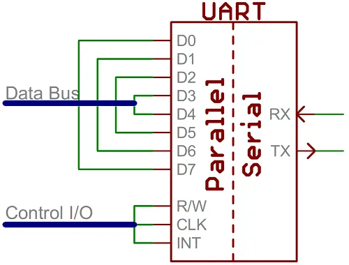
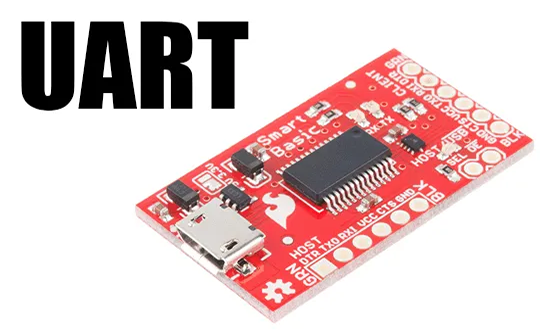
A universal asynchronous receiver/transmitter (UART) is a hardware circuit designed to enable serial data communication. In essence, the UART serves as a bridge between parallel and serial interfaces. One side of the UART features a bus of roughly eight data lines (along with several control pins), while the other side consists of just two serial wires – RX and TX.