RGB vs LVDS vs MIPI: How to Choose the Right Display Interface?
When selecting a display, size, resolution, brightness, and viewing angle are not the only parameters to consider. The Display Interface determines how the host processor communicates with the LCD and also affects the number of signal lines, PCB layout, interface bandwidth, cable design, and whether the display module can be integrated directly into the existing mainboard.
RGB, LVDS, and MIPI DSI are three common interface types used with TFT LCDs. They are not simply different connector configurations. Each uses a different signal transmission architecture, which affects data bandwidth, PCB routing, processor compatibility, cable design, and overall system integration.
For the same display size, a 1024 × 600 product may use an RGB interface, while a 1920 × 1200 high-resolution display may use MIPI DSI or LVDS. The interface should not be selected based only on display size or resolution. The host processor, pixel data rate, available I/O resources, transmission distance, PCB space, and overall system architecture all need to be considered.
This article compares RGB, LVDS, and MIPI DSI from an engineering and purchasing perspective and explains how to select a suitable Display Interface for different project requirements.
What Is a Display Interface?
A Display Interface is the electrical communication interface used to transfer image data between a display module and the host system. The host can be an MCU, MPU, CPU, SoC, industrial computer, automotive controller, or another embedded processing platform.
Depending on the interface architecture, the connection may carry pixel data, clock signals, and related control signals.
When selecting a display, engineers typically need to check the following parameters:
- Interface Type
- Data Width or Lane Count
- Pixel Clock or Data Rate
- Resolution
- Refresh Rate
- Color Depth
- Signal Voltage
- Connector and Pin Definition
- FPC Length and Direction
- PCB Routing Requirements
- Host Processor Compatibility
The basic data path can be understood as:Host Processor → Display Interface → TFT LCD Module
A display that meets the required size and resolution is not necessarily compatible with the target system. The host processor must support the corresponding interface and provide sufficient bandwidth for the required image data.
For projects with a predefined processor platform, it is recommended to check the processor datasheet and its display interface specifications first. The LCD can then be selected based on the available interface, resolution, refresh rate, and mechanical dimensions.
What Are the Differences Between RGB, LVDS, and MIPI?
RGB, LVDS, and MIPI DSI are all used to transfer image data from a host system to a display, but they use different transmission architectures.
| Comparison Item | RGB | LVDS | MIPI DSI |
|---|---|---|---|
| Transmission Method | Parallel transmission | Differential serial transmission | High-speed differential serial transmission |
| Common Host Platforms | MCU / MPU / SoC | Industrial PC / MPU / SoC | Application Processor / SoC |
| Signal Line Count | Relatively high | Lower than parallel RGB | Relatively low |
| Signal Structure | Multiple single-ended data lines | Multiple differential pairs | Clock Lane + multiple Data Lanes |
| PCB Routing | Parallel timing needs to be considered | Differential-pair routing | High-speed differential routing |
| Common Applications | Embedded HMI, industrial control | Industrial displays, fixed terminals | Smart devices, embedded systems, high-resolution displays |
| High-Resolution Expansion | Limited by data width and Pixel Clock | Suitable for higher data volumes | Suitable for high-data-volume display systems |
| Host I/O Usage | Relatively high | Lower | Lower |
| Main Design Considerations | Pin count, Pixel Clock, timing | Differential impedance, Data Mapping, timing | Lane configuration, impedance, timing, initialization |
From an engineering perspective, these three interfaces should not simply be classified as low-, medium-, and high-speed solutions. The final choice depends on the host platform, display resolution, refresh rate, data format, and PCB architecture.
RGB Interface: When Is RGB a Suitable Choice?
RGB is a common parallel Display Interface used in embedded systems and industrial control equipment.
In a typical 24-bit RGB configuration, the red, green, and blue channels use independent data lines. Depending on the LCD architecture, signals such as PCLK, HSYNC, VSYNC, and DE are also required.
As a result, a 24-bit RGB connection requires more signal lines than a serial differential interface.
Common 24-bit RGB signals include:
- 8-bit Red Data
- 8-bit Green Data
- 8-bit Blue Data
- Pixel Clock
- Horizontal Sync
- Vertical Sync
- Data Enable
For engineers familiar with MCU-based display control and parallel LCD timing, the RGB architecture is relatively straightforward.
HOTHMI’s TFT-H070A20WSIFTKN50 is a 7.0-inch TFT Display with a 1024 × 600 resolution and a 24-bit RGB interface. It provides 1000 cd/m² brightness and supports an operating temperature range of -20°C to +70°C.
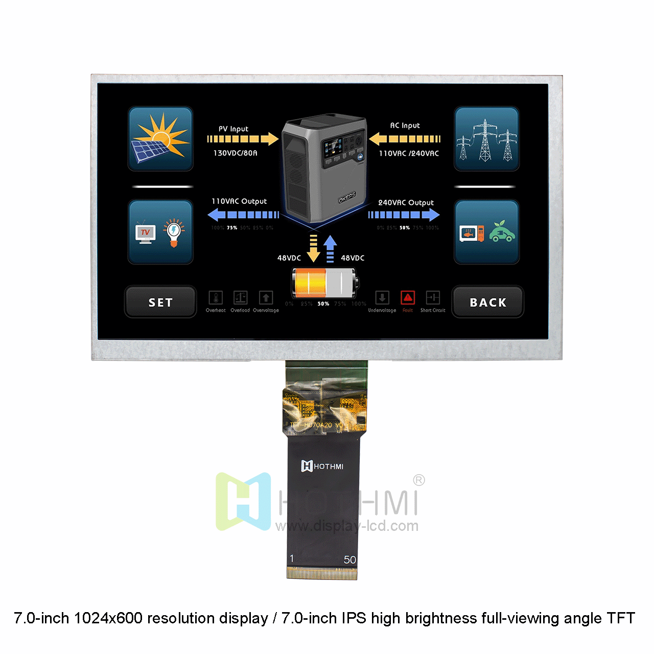
If the embedded controller already provides RGB output, an RGB display module can reduce the need for additional interface conversion circuitry.
Key Characteristics of RGB
RGB can be considered when:
- The MCU or SoC already supports RGB output;
- The mainboard has been designed with a parallel display interface;
- The system has sufficient I/O pins;
- The connection between the display and host is relatively short;
- The system requires direct control of LCD timing;
- The project involves an industrial HMI, control panel, or embedded device.
Limitations of RGB
One of the main characteristics of RGB is its relatively high signal line count.
As resolution and refresh rate increase, the Pixel Clock and data bandwidth also increase. At the same time, a large number of parallel signals switching at relatively high speed can place greater demands on PCB routing, signal integrity, and EMI control.
A 24-bit RGB interface requires multiple data lines, while MIPI DSI can transmit image data through multiple high-speed differential lanes. As a result, the two interfaces have different requirements in terms of PCB resources and signal routing.
When selecting RGB, engineers should check the available host I/O resources, Pixel Clock, data width, and PCB space together rather than evaluating the interface in isolation.
LVDS: When Should You Consider LVDS?
LVDS stands for Low-Voltage Differential Signaling.
Unlike RGB, which uses multiple single-ended parallel signals, LVDS serializes image data and transmits it through differential pairs, reducing the number of high-speed signal connections.
LVDS is widely used in industrial displays, fixed terminals, industrial computers, some automotive display systems, and TFT LCD modules.
What Are the Advantages of LVDS?
LVDS uses differential signaling, which can improve the system’s resistance to certain types of noise compared with high-speed single-ended signaling. It is therefore commonly found in industrial equipment, industrial computers, and systems containing motors, power modules, and switching devices.
LVDS Display Interface solutions can be found in applications such as:
- Industrial computers
- Automation equipment
- Industrial control terminals
- Monitoring equipment
- Vehicle-related display systems
- Fixed operating terminals
HOTHMI’s TFT-H080D13XGIYZ5N40 is an 8.0-inch TFT LCD with a 1024 × 768 resolution and 500 cd/m² brightness. It uses a 40-pin LVDS 4L interface and supports an operating temperature range of -20°C to +70°C.
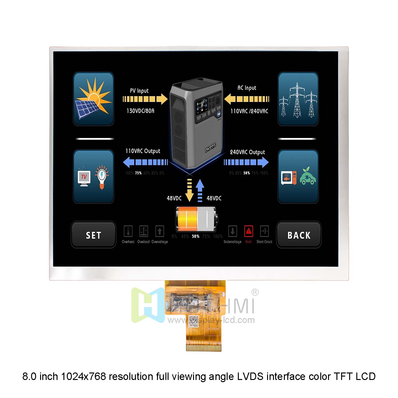
For industrial mainboards or embedded systems that already provide LVDS output, this type of display module can be matched according to the existing LVDS architecture.
What Should Be Checked When Selecting LVDS?
Engineers should not stop at confirming that the mainboard supports LVDS.
The following parameters should also be checked:
- LVDS 1-Port or 2-Port;
- LVDS Data Lane count;
- Clock configuration;
- Bit Mapping;
- VESA or JEIDA format;
- Signal Polarity;
- Connector Pin Definition;
- Differential Impedance;
- FPC / Cable Pin Assignment;
- Display Timing.
Even when two displays are both specified as LVDS, differences in data mapping, channel configuration, or timing can prevent direct replacement.
For example, some HOTHMI LVDS products specify 1-Port or 2-Port configurations together with the corresponding bit format. If the LVDS data mapping does not match the host configuration, the display may show incorrect colors, image distortion, or fail to display even when the connector is mechanically compatible.
MIPI DSI: Why Is It Widely Used in Embedded and Smart Devices?
MIPI DSI is a high-speed serial Display Interface developed for mobile devices and embedded systems.
Unlike parallel RGB, MIPI DSI uses high-speed differential Data Lanes to transfer display data. A typical configuration can include one Clock Lane and multiple Data Lanes.
A 4-Lane MIPI DSI interface typically uses four differential data lanes together with a clock lane. Compared with 24-bit RGB, this architecture can reduce the number of high-speed signal connections and allow a more compact connection between the display module and host processor.
Key Characteristics of MIPI DSI
MIPI DSI is commonly considered for systems with requirements such as:
- Limited PCB space;
- Limited host I/O resources;
- Higher display resolution;
- Native MIPI DSI support from the processor or SoC;
- Fewer high-speed signal connections;
- Compact FPC design.
MIPI DSI is commonly found in embedded Linux, Android, smart terminals, portable devices, industrial computers, and other systems based on ARM or application processors.
HOTHMI’s HTM-H080D16-MIPI-A01C is an 8.0-inch 1920 × 1200 WUXGA TFT LCD with a MIPI DSI 4-Lane interface. It provides 1500 ± 100 cd/m² brightness and supports an operating temperature range of -30°C to +85°C. The product is available with or without touch. The CTP version uses a GT911 controller and supports up to 5-point touch.
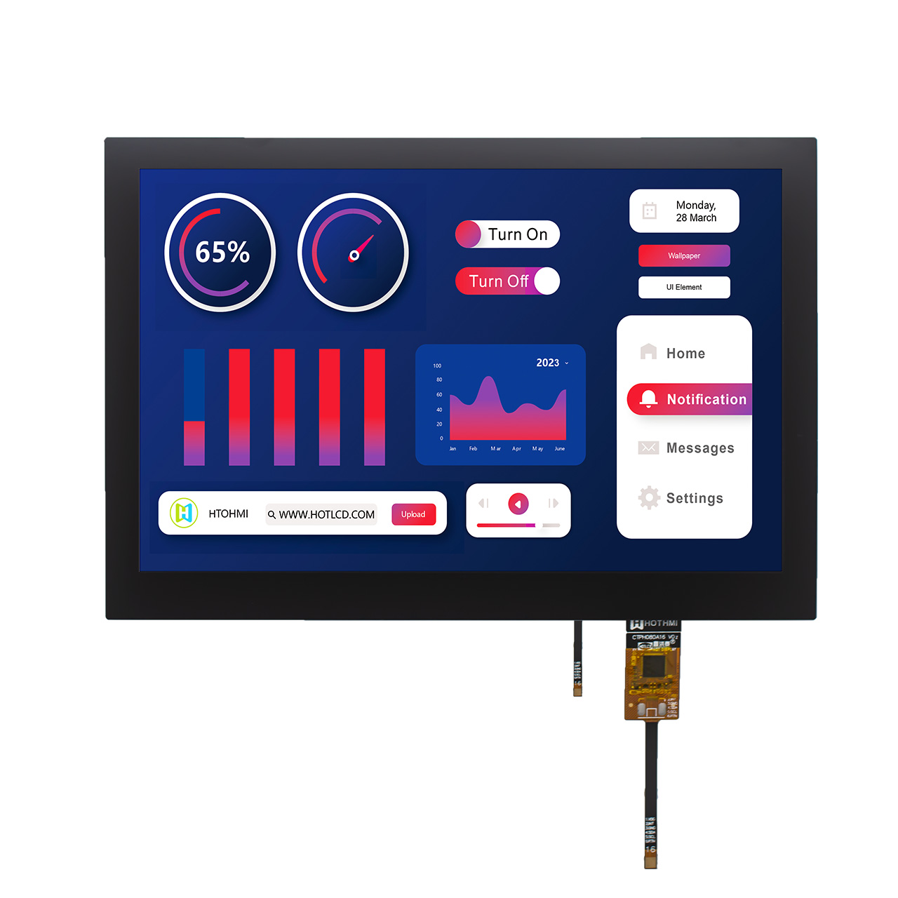
For embedded processors, industrial HMI systems, or Raspberry Pi-class platforms using MIPI DSI, this type of module can be used as a high-resolution display solution.
How Should You Choose Between RGB, LVDS, and MIPI?
Interface selection should start with the host processor, rather than with the LCD specifications.
Consider RGB when:
- The MCU or SoC already provides RGB output;
- The mainboard has a parallel display interface;
- The system needs direct control of LCD timing;
- The MCU has sufficient I/O resources;
- The PCB has enough routing space;
- The project has specific requirements for interface complexity.
Typical applications include industrial HMIs, control panels, embedded instruments, and equipment displays.
Consider LVDS when:
- The mainboard already provides LVDS output;
- The display system is designed for industrial or fixed equipment;
- The project uses a differential display signal architecture;
- There is a relatively long connection between the display and mainboard;
- The design needs to avoid a large number of parallel RGB signal lines.
Typical applications include industrial PCs, automation equipment, vehicle-related equipment, monitoring devices, and industrial display terminals.
Consider MIPI DSI when:
- The main processor natively supports MIPI DSI;
- PCB space is limited;
- A compact FPC connection is required;
- Display resolution or data volume is relatively high;
- The system is based on Android, Linux, ARM, or an application processor;
- The design needs to reduce the number of high-speed signal connections.
Typical applications include smart terminals, embedded computers, industrial tablets, high-resolution HMIs, and portable devices.
These conditions are reference points rather than absolute rules. The same resolution can be implemented with RGB, LVDS, MIPI, or other interface configurations. The final choice still needs to be confirmed against the native display output capability of the host processor.
Calculate Display Bandwidth Before Selecting the Interface
One aspect that is easily overlooked in display projects is that Display Interface selection should not be based on resolution alone.
The amount of display data depends on several parameters:
Display Data Rate ≈ Horizontal Pixels × Vertical Pixels × Refresh Rate × Bits Per Pixel
For a 1920 × 1200, 60 Hz, 24-bit Color display:1920 × 1200 × 60 × 24 ≈ 3.32 Gbit/s
This represents the basic pixel data rate.
The actual interface bandwidth requirement can also be affected by protocol overhead, data packets, blanking intervals, encoding methods, and other factors. Therefore, the 3.32 Gbit/s figure should not be treated as the final interface bandwidth requirement.
For a 1920 × 1200 display at 60 Hz with 24-bit color, the basic pixel data rate is approximately 3.32 Gbit/s. The actual interface capability required by the host should be determined together with the specific interface protocol and display timing.
Engineers should also verify:
- Processor Maximum Bandwidth;
- MIPI Lane Count;
- LVDS Channel Count;
- Pixel Clock;
- Refresh Rate;
- Color Depth;
- Display Timing;
- Video Mode or relevant Interface Configuration.
How Do RGB, LVDS, and MIPI Affect PCB Layout?
Different Display Interface architectures also create different PCB design requirements.
RGB PCB Layout
RGB uses multiple parallel signals, so engineers should pay particular attention to:
- Trace Length;
- Clock and Data Timing;
- Signal Integrity;
- Ground Reference;
- Crosstalk;
- EMI;
- Connector Pin Assignment.
As the Pixel Clock increases, timing matching between the data lines and clock becomes increasingly important.
LVDS PCB Layout
LVDS uses differential pairs and requires controlled differential routing.
Key considerations include:
- Differential Impedance;
- Pair Matching;
- Intra-Pair Skew;
- Inter-Pair Skew;
- Reference Plane;
- Connector;
- FPC Structure.
The specific impedance requirement should follow the electrical specifications provided by the LCD and PCB suppliers rather than applying one fixed value to every design.
MIPI PCB Layout
MIPI DSI is a high-speed differential interface, so the PCB should be designed according to high-speed signal integrity requirements.
Important items include:
- Differential Impedance;
- Pair Length Matching;
- Lane Assignment;
- Clock / Data Routing;
- Via Count;
- Connector;
- FPC Impedance;
- Power Integrity;
- EMI.
MIPI uses fewer high-speed signal lines, but that does not necessarily mean the PCB design is simpler. The quality of high-speed differential routing can still have a direct impact on display stability.
FAQ of Display Interface
Q1. Can an RGB display be directly replaced with an LVDS or MIPI display?
Usually, it cannot be directly replaced.
RGB, LVDS, and MIPI use different electrical signaling architectures. If the host processor only provides RGB output while the target LCD uses LVDS or MIPI, an appropriate bridge IC or interface conversion solution may be required.
Before changing the Display Interface, engineers need to confirm whether the host processor or display controller natively supports the target interface.
A matching connector alone does not mean that two display modules are electrically interchangeable.
Q2. Does a high-resolution display always require MIPI or LVDS?
Not necessarily.
Resolution alone does not determine the Display Interface. As long as the host can provide sufficient Pixel Clock, data bandwidth, and I/O resources, RGB can also be used for displays with different resolutions.
However, as resolution and refresh rate increase, the number of parallel RGB signals and high-speed signal requirements also increase. In such cases, whether LVDS or MIPI is more suitable depends on the host platform and PCB architecture.
Q3. Which interface is easier to integrate: RGB, LVDS, or MIPI?
It depends on the host platform.
If the MCU already provides RGB output, an RGB display module may not require additional interface conversion.
If the application processor natively supports MIPI DSI, MIPI can reduce the number of high-speed signal connections.
If an industrial mainboard already uses LVDS output, an LVDS display may fit the existing hardware architecture more directly.
Display Interface Selection Checklist
Before finalizing an LCD, engineers can use the following checklist:
- Does the host processor support RGB, LVDS, or MIPI DSI?
- Does the host support the target resolution?
- Is the Pixel Clock sufficient?
- Is the Interface Bandwidth sufficient?
- Does the MIPI Lane Count match?
- Does the LVDS Channel configuration match?
- Does the RGB Data Width match?
- Are the Signal Voltage levels compatible?
- Does the Connector Pin Definition match?
- Do the FPC dimensions and direction fit the mainboard design?
- Does the PCB meet high-speed signal integrity requirements?
- Does the operating temperature meet the device environment?
- Is the Brightness suitable for the actual application environment?
- Is a Touch Panel required?
- Can the Mechanical Outline fit the product enclosure?
Display Interface selection should not be treated as an isolated LCD specification. It needs to be evaluated together with the host processor, display timing, PCB, mechanical structure, and overall electrical design.
For embedded and industrial projects using RGB, LVDS, or MIPI DSI, HOTHMI provides TFT LCD modules with different interface configurations and can also support customized display solutions based on project requirements, including LCD size, Touch Panel, FPC, Connector, Backlight, PCB, and mechanical structure.
Confirming the Display Interface at an early stage can reduce interface compatibility issues during prototype development and make the transition from sample validation to mass production more predictable.
HOTHMI Display Interface Customization Support
If you have specific Display Interface or display requirements that cannot be met by a standard product, feel free to contact HOTHMI. We support customized display solutions, including display size, resolution, brightness, touch technology, Display Interface, FPC, and driver IC. Share your controller model and project requirements with our engineering team, and we can assist with display selection and solution matching.