Operating Principles of a Four-Wire Resistive Touch Display
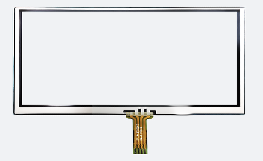
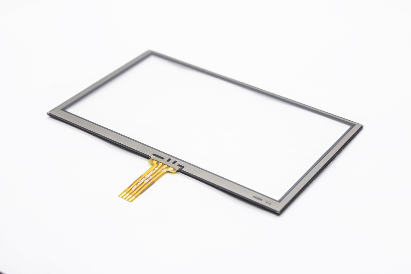
A resistive touch display functions as a transducer that maps the physical position of a touch point within a rectangular area into voltage signals corresponding to the X and Y coordinates. Such touch panels are frequently integrated into LCD modules. Based on their construction, resistive touch displays come in several variants, including four-wire, five-wire, and other multi-wire types. Among these, the four-wire configuration is the most prevalent. This section will concentrate on the operational mechanism of the four-wire resistive touch panel.
Fundamental Principle of Resistive Touch Displays
At their core, resistive touch displays rely on pressure detection to manage and interact with on-screen content. The panel is composed of two highly transparent conductive layers, which are normally kept separate by an insulating gap. When a finger presses against the screen, these two conductive layers make contact exactly at the touched location. One of these layers is supplied with a steady 5V electric field along the Y-axis direction; upon contact, the voltage on the sensing layer shifts from zero to a measurable value. The control electronics detect this change, perform an analog-to-digital (A/D) conversion, and compare the resulting voltage against the 5V reference. From this comparison, the Y-axis coordinate of the touch point is derived. The X-axis coordinate is obtained in a similar manner. This basic principle underpins all resistive touch technologies.
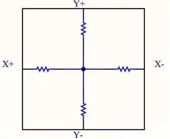
Detailed Operation of a Four-Wire Resistive Touch Display
When a user applies pressure to the outer surface of the screen, the flexible PET film deforms and bends inward, causing the upper and lower ITO (indium tin oxide) coatings to meet at the point of contact. An analog-to-digital converter (ADC) then measures the voltage at this junction, from which the X and Y position values are calculated.
The step-by-step operation of a four-wire resistive touch display proceeds as follows:
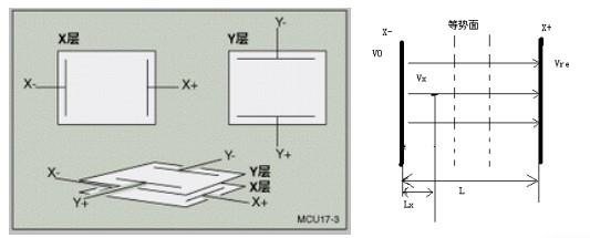
- A fixed reference voltage Vref is applied across the X+ and X– electrodes, while the Y+ terminal is connected to an ADC with a high input impedance.
- Between the X+ and X– electrodes, the electric field is uniformly distributed along the X direction.
- Upon touch, the two conductive layers connect at the contact point. The voltage present on the X-layer at that point is then transferred to the Y-layer and read by the ADC.
- This measured voltage, Vx, is used in the ratio Lx / L = Vx / Vref, where L is the total length, to compute the X coordinate.
- To obtain the Y coordinate, the same procedure is followed: Vref is applied to the Y+ and Y– electrodes, and the X+ lead is connected to the high-impedance ADC for voltage acquisition.
Beyond determining the X and Y positions, the four-wire resistive panel is also capable of gauging the contact pressure. Higher pressure results in more intimate contact between the conductive layers, which reduces the contact resistance. By measuring this resistance, the applied pressure can be estimated. Since the measured voltage is directly proportional to the coordinate value, calibration is necessary—specifically, by checking for any offset in the voltage reading at the (0,0) origin point—to ensure accurate positioning.
A version of this post was first published on https://www.display-lcd.com/news_details/68.html?.
To find out more about our products, click here.