Connecting MCU, MPU, or CPU to LCD: An Introduction to the LVDS Interface
There are multiple ways to connect a Microcontroller Unit (MCU), Microprocessor Unit (MPU), or Central Processing Unit (CPU) to an LCD display. Among these connection methods, the LVDS interface stands out as one of the most widely adopted solutions, particularly for high-performance display applications.
Basic Knowledge (Part 1): LCD Driving Waveform
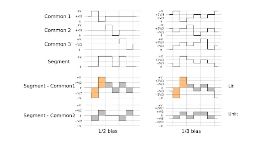
An LCD panel cannot be driven by direct current (DC); it requires an alternating current (AC) driving signal, with the net current over time maintained at zero. If a DC component is present, the liquid crystal material will inevitably degrade and become damaged over time.
Basic Knowledge (Part 2): LCD Controller vs. Driver
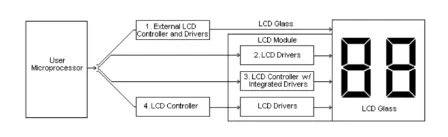
Driver ICs are generally classified into two categories: Common Drivers and Segment Drivers. Common Drivers generate scanning signals that define the rows or number of lines on the display. Segment Drivers, on the other hand, output the pattern signals required to form characters, symbols, or columns.
A Controller IC receives display data—typically encoded in ASCII or JIS format—from the MPU and stores it in its internal RAM. This data is then converted into serial character patterns and transmitted to the LCD driver ICs for rendering on the screen.
In many graphic display modules, the Drive/Controller IC is the most commonly used integrated solution. This type of IC not only receives and stores data from the MPU but also directly accepts commands from the MPU to manage both the common and segment drivers, simplifying overall system design.
Understanding the LVDS Interface
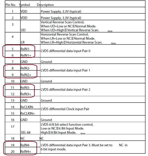
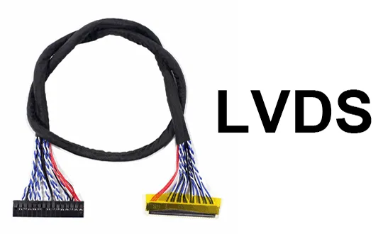
LVDS (Low-Voltage Differential Signaling) is a high-speed electrical digital signaling standard that enables reliable data transmission over low-cost twisted-pair copper cables. Its core operating principle involves transmitting data through a complementary pair of differential signal lines (P and N). The receiving end detects logic states by measuring the voltage difference between these two lines, with a typical differential swing of 350 mV.
This differential signaling architecture, combined with a 100Ω termination resistor at the receiver, gives the LVDS interface exceptional common-mode noise rejection and very low electromagnetic interference (EMI). As a result, signal integrity remains robust even over longer cable runs and in electrically noisy environments.
Due to these advantages, the LVDS interface is especially well-suited for large-size panels that demand high display quality and strong anti-interference performance—commonly found in laptop screens, flat-panel televisions, industrial monitors, and automotive displays. In practice, LVDS is predominantly used in panels larger than 7 inches diagonally.
It is important to note that LVDS defines only the physical layer specifications. Higher-level display interface standards, such as OpenLDI and FPD-Link, build upon the LVDS physical layer by adding data encoding, packetization, and transmission protocol definitions at the data link layer. Understanding this distinction is key when evaluating display interface options for different system-on-chip (SoC) or graphics processor platforms.