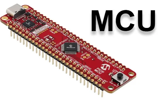
Understanding the MCU Interface: The Parallel Communication Bridge Between MCU and LCD
In embedded system design, enabling communication between a microcontroller or microprocessor and a liquid crystal display is fundamental to building human-machine interfaces. Among the various communication methods available, the MCU interface (also known as the parallel interface or microprocessor interface) stands out as a time-tested, widely adopted, and classic approach. This article provides a comprehensive yet accessible introduction to the principles, classifications, advantages, limitations, and application scenarios of the MCU interface, along with essential underlying LCD driving and hardware architecture knowledge.
Essential Basic Knowledge of LCD Driving and Hardware Architecture
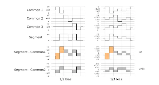
LCD Driving Waveform Principle
LCD panels cannot be driven by direct current signals and require alternating current driving with an overall zero current balance. Long-term DC driving will cause irreversible electrochemical damage to the internal liquid crystal material, leading to permanent degradation of display performance, and even complete failure of the LCD screen. Therefore, all formal LCD driving schemes adopt AC alternating driving mode to protect the liquid crystal medium and ensure a long service life of the display module.
LCD Hardware Hierarchical Architecture: Controller vs. Driver
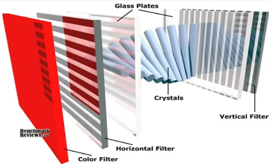
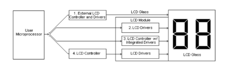
The internal hardware of a standard LCD module follows a mature hierarchical architecture, mainly composed of an LCD Controller IC and two types of Driver ICs (Common Driver and Segment Driver), which cooperate to complete display data processing and screen rendering.
The LCD Controller is the core control unit of the module. It is responsible for receiving commands and display data transmitted from the host MCU/MPU, caching the received data in the internal RAM, and converting coded data such as ASCII and JIS into standard dot-matrix character and graphic patterns. It uniformly issues control instructions to coordinate the work of subsequent driver ICs.
The Common Drivers and Segment Drivers are responsible for the physical rendering of pixels. Common Drivers output periodic sequential row scanning signals to control the on-off state of each horizontal row of the LCD screen; Segment Drivers output corresponding column data signals according to the graphic patterns converted by the controller, realizing the precise lighting of column pixels. The combination of row and column signals finally presents complete characters and images on the LCD panel.
What Is the MCU Interface?
The MCU interface generally refers to a parallel communication protocol that allows an MCU or MPU to directly exchange data with the controller embedded within an LCD module. This interface standard traces its origins to Intel’s 8080 bus architecture, which is why it is frequently referred to as the I80 interface in many technical documents.
In essence, through the MCU interface, the MCU writes display data into the Graphic RAM built into the LCD module. The LCD driver then continuously refreshes the screen with the content stored in the GRAM, rendering the image. This refresh process is independently managed by the LCD driver, without requiring the MCU to supply continuous clock or synchronization signals—significantly reducing the burden on the MCU.
The Two Main Branches: 8080 Mode vs. 6800 Mode
The MCU interface is primarily divided into two control modes: 8080 mode and 6800 mode. Their core distinction lies in how read and write operations are controlled.
- 8080 Mode (Intel Standard): Uses separate “Read Enable” and “Write Enable” control lines for read and write operations. This is by far the more popular and widely adopted mode.
- 6800 Mode (Motorola Standard): Uses a single “Read/Write Select” line to differentiate between read (high level) and write (low level), while adding an “Enable” line that serves as a strobe/clock signal for data latching.
Aside from the differences in control signals, the other core signal lines function identically across both modes and typically include:
| Signal | Description |
|---|---|
| DB0–DB7 | 8‑bit bidirectional data bus (8‑bit width is the most common, though 4‑, 9‑, and 16‑bit variants also exist) |
/CS | Chip Select, used to activate the specific LCD module |
| RS | Register Select, which distinguishes whether the current transfer is a command or data |
/RESET | Reset signal, used to initialize the LCD module |
Advantages and Limitations of the MCU Interface
The enduring popularity of the MCU interface in embedded systems—particularly for small‑sized displays—can be attributed to its distinctive characteristics.
Advantages: Simple, Direct, and Reliable
| Advantage | Explanation |
|---|---|
| Simple Control Logic | The parallel interface timing is straightforward and intuitive. Unlike serial interfaces such as SPI or I²C, there is no complex protocol stack to handle—the MCU can directly read from and write to the bus. |
| No Synchronization Clock Required | Because data is written directly into GRAM, the LCD refresh is internally driven by the LCD controller. This eliminates the need for synchronization signals like HSYNC and VSYNC, which are mandatory for RGB interfaces. |
| Cost‑Effective on the Host Side | For static or slow‑changing display content at moderate resolutions, the MCU interface eliminates the need for additional display controllers on the MCU/MPU side, reducing overall system BOM cost. |
Limitations: The Ceiling of Speed and Size
| Limitation | Explanation |
|---|---|
| Speed Constraints | Data is transferred via the parallel bus, which has an inherent upper speed limit. Furthermore, the MCU must participate in every GRAM write operation, which restricts the achievable refresh rate—making this interface ill‑suited for video playback or smooth animation. |
| Requires GRAM | The LCD module must incorporate GRAM internally, which adds to both the cost and complexity of the module. Additionally, the GRAM capacity imposes a practical ceiling on the maximum resolution supported, which is why the MCU interface is typically used for screens 3.5 inches or smaller. |
Application Scenarios: From Character Displays to Small‑Size TFTs
It is precisely these characteristics that determine where the MCU interface sees the most use:
- Monochrome Character/Graphic LCDs: Classic modules such as 12864 and 1602 character‑type or monochrome dot‑matrix displays are quintessential applications of the MCU interface.
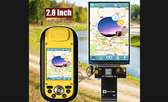
- Small‑Size TFT Color Screens: In industrial instrumentation, smart home appliances, handheld devices, and other applications that require static images or simple user interfaces, TFT screens under 3.5 inches widely adopt the MCU interface.
Summary
The MCU interface has earned its place as one of the most classic parallel communication methods for connecting MCUs to LCDs, thanks to its simplicity, ease of use, and proven reliability. By temporarily buffering display data in the module’s internal GRAM, it significantly offloads the host MCU/processor. While it does have inherent limitations when it comes to rendering dynamic content or driving large‑size panels, the MCU interface remains a top choice for engineers in small‑size, low‑cost static display applications. A solid understanding of how it works and where it excels is key to selecting the right display solution for your project.