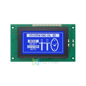

Chip on Glass 3.1 inch 12848 ST7565R LCD
- Model: HTG12848A-01Y
- Type: 128×48 Graphic Dot Matrix COG
- Overall dimensions (mm): 81.1×38.3×4.9
- VA size (mm): 75.3×28.3
- Working temperature: -20-70℃
- Supply voltage: 3.3V
- Driver chip: ST7565R
$10.80
In stock

This item: Chip on Glass 3.1 inch 12848 ST7565R LCD
$10.80
$10.80
Description
Product Overview and Core Technology
What is Chip on Glass Technology?
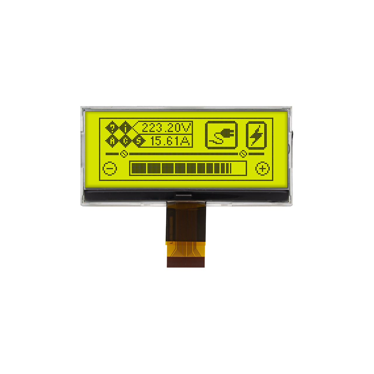
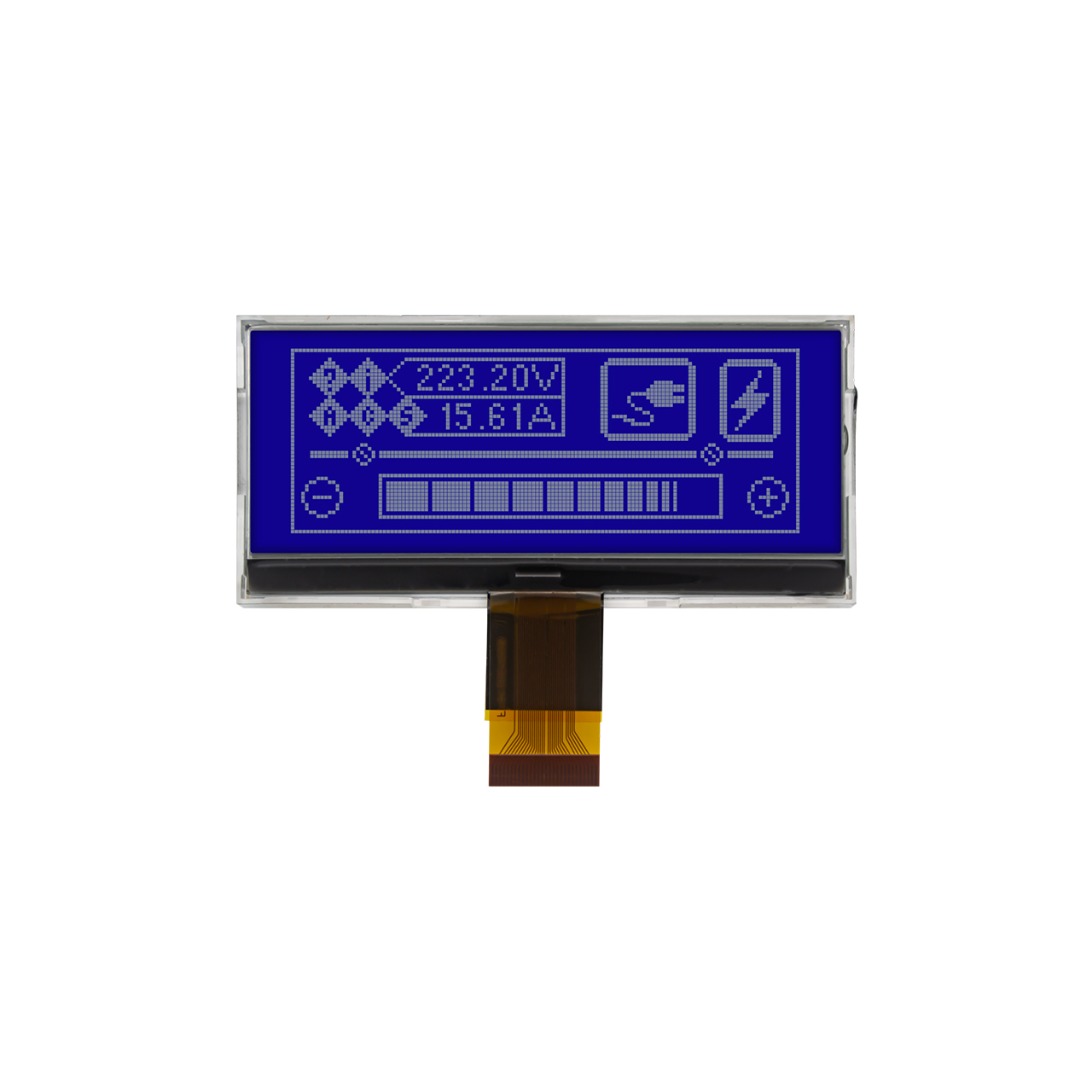
In modern industrial and consumer electronics display fields, lightweight design and high integration are core trends. The HTG12848A is a high-quality monochrome dot matrix LCD module independently developed by HOTHMI. This product adopts the advanced Chip on Glass (COG) packaging process.
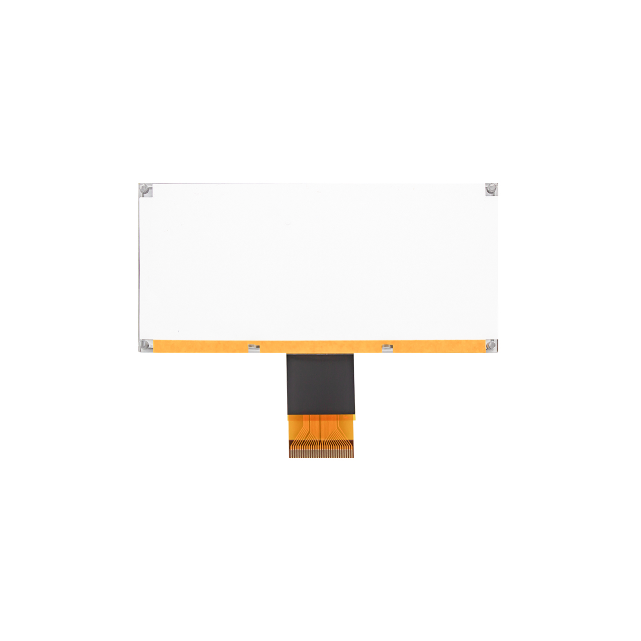
Chip on Glass technology refers to bonding the LCD driver control chip (this model uses the classic high-performance ST7565R chip) directly onto the surface of the LCD glass. This process eliminates the traditional PCB board and pin connectors, greatly reducing the module’s volume, thickness, and overall power consumption, while significantly improving signal transmission anti-interference capability and physical structural stability.
Core Product Highlights
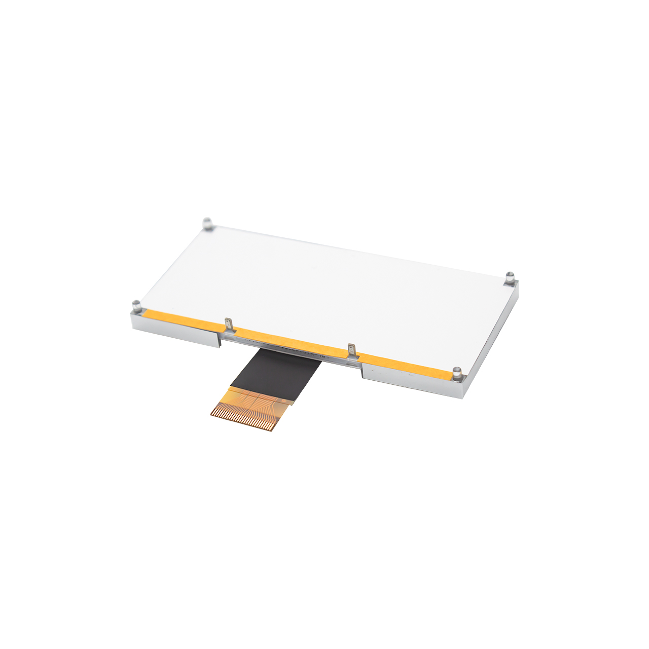
- Ultra-Thin Chip on Glass Structure
Thanks to the Chip on Glass process, the total module thickness is only 2.8mm. This ultra-thin feature makes it an ideal choice for handheld portable devices, compact industrial control panels, and space-constrained instrument panels.
- Industrial Grade Wide Temperature Tolerance
This module offers excellent environmental adaptability, with an operating temperature range of -20°C to +70°C and a storage temperature range of -30°C to +80°C. It operates stably in extreme cold or industrial high-heat environments without condensation or display color abnormalities.
- Micro-Power Design
The single-chip Chip on Glass bonding simplifies circuit losses. Its typical operating current (Iop) at 3.0V is only 100μA to 220μA. In sleep mode, typical current is only 0.1μA (maximum not exceeding 4μA). The extremely low static power consumption significantly extends battery life in portable devices.
- High Hardware Integration
The built-in ST7565R driver chip has high integration, including an internal DC-DC converter, voltage regulator, and voltage follower. Internal boost and bias control can be enabled via pure software configuration, greatly simplifying peripheral circuit design.

Circuit Diagram
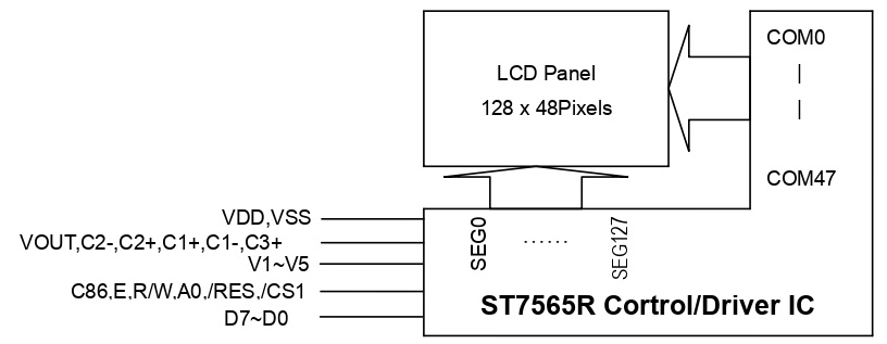
This is a typical hardware wiring diagram for the LCD module connected to an AT89S51 microcontroller, divided into three main parts:
Communication Mode Configuration (top left truth table): Pin 2 (P/S) is connected to VDD (high level), indicating parallel bus operation. By controlling Pin 3 (C86) high or low, switching between 6800 mode and 8080 mode is possible.
Peripheral Capacitors (left side Pins 4–14): Nine 1μF/25V capacitors are connected. Among them, C6, C7, and C8 are used for the internal charge pump boost, while the others are for driver voltage filtering to ensure stable display.
MCU Control Connections (right side): D7–D0 are connected to the MCU’s P1.7–P1.0 for data/command transmission. E, R/W, A0, /RES, and /CS1 are respectively connected to the MCU’s P3 port for read/write, reset, and chip select control lines.
Technical Q&A
Q1: What are the specific performance advantages of the COG process used in the HTG12848A compared to traditional COB packaging?
Answer:
Traditional COB (Chip on Board) process involves bonding the bare chip onto a PCB board, then connecting it to the LCD glass via a housing or conductive rubber strips. In contrast, the Chip on Glass process directly bonds the ST7565R driver chip onto the LCD glass. The core advantages are:
Extremely Thin and Light: Eliminates the bulky PCB, reducing total module thickness to just 2.8mm, greatly saving internal space in end products.
High Reliability: Direct chip-to-glass electrode interconnection greatly reduces solder joints, fundamentally eliminating contact issues caused by aging or vibration of traditional pins or rubber strips, offering better vibration and mechanical shock resistance.
Lower System Cost: Simplifies peripheral circuit hardware design and facilitates large-scale automated assembly.
Q2: How do I configure the
Chip on Glass
module pins to switch between 8080 parallel interface mode and SPI serial interface mode?
Answer:
According to the product terminal function specification, interface mode switching is achieved by configuring Pin 2 (P/S) and Pin 3 (C86):
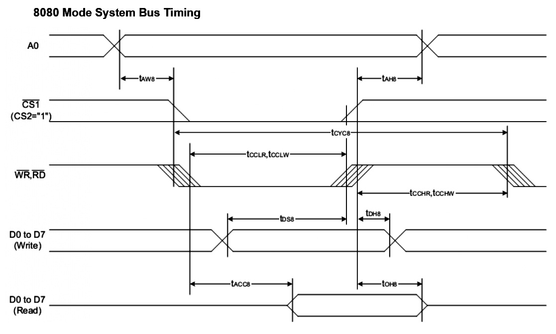
To switch to 8080 parallel mode: Set Pin 2 (P/S) to “H” and Pin 3 (C86) to “L”. Then the data bus D7–D0 is activated, Pin 24 (E) acts as active-low read signal /RD, and Pin 25 (R/W) acts as active-low write signal /WR.
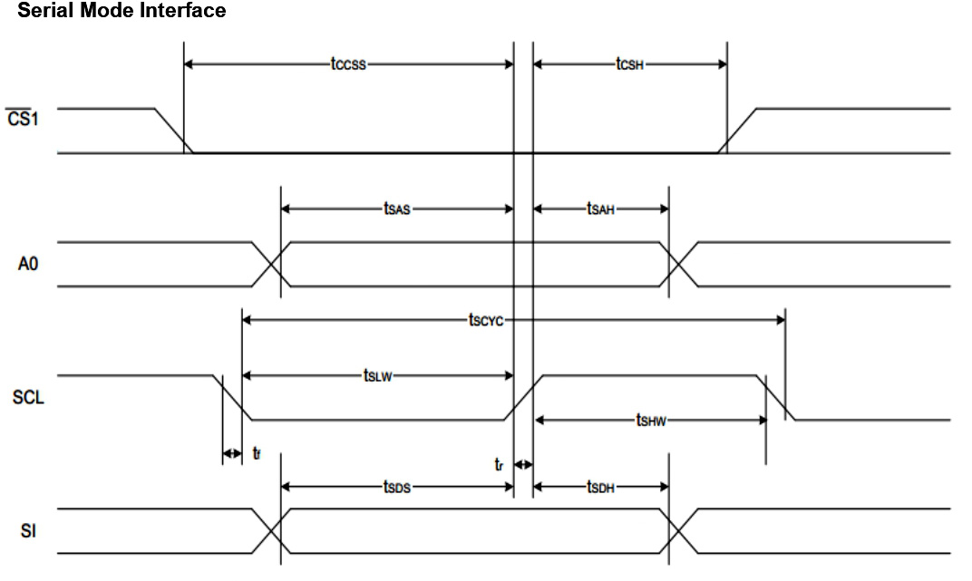
To switch to SPI serial mode: Set Pin 2 (P/S) to “L”. The parallel bus is disabled, Pin 16 (D7) automatically becomes the serial data input (SI), and Pin 17 (D6) automatically becomes the serial clock input (SCL). This mode greatly saves host MCU I/O pin resources.
Additional information
| Weight | 0.4 kg |
|---|
Attributes
| PARAMETER | SPECIFICATION CONTENT | UNIT |
| Name | HTG12848A-01Y | |
| Graphic display | 128 × 48 | dots |
| Dimensions | 81.1 x 38.3 x 4.9 (MAX) | mm |
| VA size | 75.3 x 28.3 | mm |
| AA size | 66.52 x 24.92 | mm |
| Pixel pitch | 0.52 x 0.52 | mm |
| Driver chip | ST7565R | |
| Applied voltage | 3.3V | V |
| Backlight illumination | Yellow-green | |
| Display mode | STN(+) | |
| Drive mode | 1/48 duty cycle | |
| Product type | Graphic COG | |
| Polarizer type | Transflective |
Related products