How to Choose an MCU Display: An Engineering Guide to MCU Display Selection
Choosing a display for an embedded device requires more than matching the screen size to the product. The MCU’s processing capability, memory resources, and hardware interface all need to be considered. A TFT LCD that appears suitable on paper can still cause problems during development if the interface bandwidth is insufficient, the GRAM capacity is not appropriate, or the MCU does not have enough RAM for the UI buffer.
An MCU Display is commonly used in industrial controllers, instrumentation, medical equipment, POS terminals, smart home appliances, portable devices, and embedded HMI systems. Common interfaces include 8080, 6800, and SPI. Each interface has different requirements for resolution, refresh methods, and UI complexity.
For engineers, MCU Display selection should focus less on screen size alone and more on whether the MCU resources, display interface, resolution, Driver IC, GRAM, color depth, refresh requirements, and mechanical design work together.
This guide looks at MCU Display selection from both hardware and software perspectives.
What Is an MCU Display?
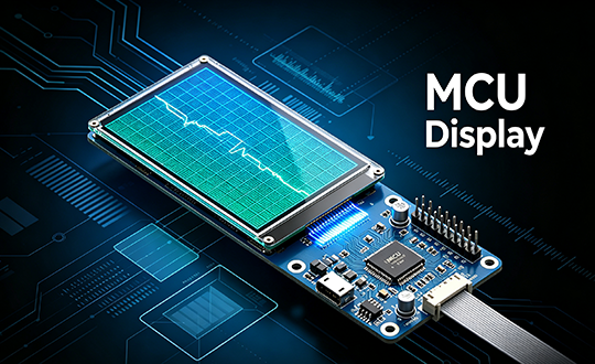
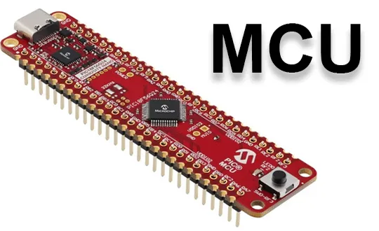
An MCU Display generally refers to a TFT LCD solution that communicates with the main MCU through an MCU interface.
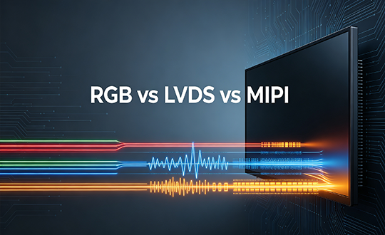
Unlike high-speed display interfaces such as MIPI DSI and LVDS, an MCU Display commonly uses an LCD Driver IC with built-in GRAM. The MCU sends display data to the Driver IC through an 8080, 6800, or SPI interface, while the Driver IC controls the TFT LCD panel.
A typical MCU Display structure includes:
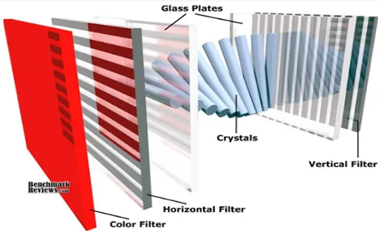
- TFT LCD panel
- LCD Driver IC
- GRAM
- MCU interface
- FPC or connector
- LED backlight
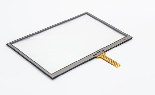
- RTP or CTP touch panel, optional
One advantage of this architecture is that part of the display control can be handled by the Driver IC. The MCU does not necessarily need to continuously generate the complete LCD scanning signals, and display data can be stored in the Driver IC’s internal GRAM.This architecture can be practical for embedded systems with limited resources.
For example, a compact instrument may only need to display temperature, pressure, speed, icons, and several menu pages. In such a case, a TFT LCD module with an MCU interface may be sufficient without using a more complex high-speed display architecture.
Start With the MCU, Not the Display
Before selecting an MCU Display, start by checking the main MCU.
| MCU Parameter | Impact on the Display System |
|---|---|
| RAM | Determines Frame Buffer and UI buffer capacity |
| Flash | Determines the available space for fonts, images, and UI resources |
| CPU performance | Affects GUI rendering and data processing speed |
| LCD interface | Determines which display solutions can be used |
| SPI speed | Affects data transfer performance for SPI Display |
| DMA | Affects display data transfer efficiency |
| External Memory Interface | Can be used to connect an 8080 LCD or external RAM |
| GPIO count | Affects the hardware connection of a parallel MCU interface |
If the project uses an STM32 MCU, the specific series and part number should be checked.
Some STM32 MCUs provide FSMC or FMC external memory interfaces that can be used with an 8080 MCU Display. With a 16-bit parallel LCD, the MCU’s external memory interface can be used for display data access.
From the software side, the LCD can often be mapped in a way similar to external memory. DMA or dedicated driver mechanisms can then be used to improve data transfer efficiency.
STM32 devices do not all provide the same peripheral resources, so compatibility should not be determined simply by whether the MCU family supports LCD applications.
Calculate Frame Buffer Requirements
RAM is one of the most commonly underestimated factors in MCU Display selection.
With RGB565, each pixel uses 2 bytes.
The basic calculation is:Frame Buffer = Width × Height × 2 Bytes
320 × 240 Display:320 × 240 × 2 = 153,600 Bytes
Approximately 150 KB.
480 × 272 Display:480 × 272 × 2 = 261,120 Bytes
Approximately 255 KB.
480 × 800 Display:480 × 800 × 2 = 768,000 Bytes
Approximately 750 KB.
If the MCU has only 128 KB of internal SRAM, a full-screen Frame Buffer for a 480 × 800 RGB565 display cannot be stored directly in internal RAM.
Possible approaches include:
- Using external RAM
- Using the Driver IC’s internal GRAM
- Using partial refresh
- Reducing the number of Frame Buffers
- Lowering the UI resolution
- Adjusting the buffer strategy according to the GUI framework
The actual memory requirement can be higher than the Frame Buffer calculation. A GUI system may require two Frame Buffers, as well as additional memory for fonts, images, widgets, and temporary drawing operations.
Choose the MCU Display Interface
The interface has a direct effect on both hardware design and display performance.
8080 MCU Interface
8080 is a common parallel interface for embedded TFT LCD applications.
Typical signals include:
- D0–D7 / D0–D15
- CS
- RS / DC
- WR
- RD
- RESET
Depending on the display module, an 8-bit or 16-bit data bus can be used.
For RGB565 displays, a 16-bit interface is common because one pixel can be transferred using 16 bits of data.
If the STM32 MCU provides an FSMC or FMC external memory interface, an 8080 MCU Display can generally be connected through that interface.
Suitable applications include:
- Industrial instruments
- Compact HMI systems
- Medical equipment
- POS terminals
- Controllers
- Low- to medium-resolution TFT LCD applications
6800 MCU Interface
The 6800 interface uses a similar basic data transfer concept to the 8080 interface, but the read and write control signals are different.
Engineers need to check whether the selected MCU supports the required interface directly or whether the timing needs to be controlled through GPIO.
When GPIO-based control is used, software efficiency and CPU load should be evaluated as part of the design.
For a project with a fixed MCU platform, selecting an MCU Display that matches the MCU’s available hardware peripherals can simplify development.
SPI Interface
One of the main advantages of SPI is the small number of signal lines required.
A typical SPI Display may use:
- SCLK
- MOSI
- CS
- DC
- RESET
This can reduce PCB routing requirements, particularly in compact devices.
The limitation is data throughput. As the amount of display data increases, the SPI interface can become a bottleneck.
For a 320 × 240 RGB565 display, one full frame contains approximately 153.6 KB of data.
At a target refresh rate of 30 fps:
153.6 KB × 30 ≈ 4.6 MB/s
This calculation does not include command data, control data, or other protocol overhead.
SPI can work well when the UI only updates a few numbers or icons. Full-screen animation, rapidly changing waveforms, or high-refresh-rate interfaces require actual performance testing before the interface is selected.
How to Calculate MCU Display Bandwidth?
Frame Buffer size is only one part of the calculation. Interface bandwidth also needs to be considered.
For a 480 × 272 RGB565 display:480 × 272 × 16 bit = 2,088,960 bit
The frame data is approximately 261 KB.
At 30 fps:261 KB × 30 ≈ 7.83 MB/s
This is a theoretical data requirement.
Actual system performance also depends on:
- Interface clock
- DMA efficiency
- MCU CPU load
- Driver IC timing
- GUI rendering speed
- Command overhead
- Partial refresh strategy
If only a small area of the UI changes, the actual amount of display data can be significantly lower.
For example, when a temperature value changes from 25°C to 26°C, only the numerical area needs to be updated. There is no need to retransmit the entire screen.
For industrial instruments, measurement devices, and controllers, partial refresh can be a more practical approach than simply increasing the target refresh rate.
Check the LCD Driver IC and GRAM
The specific Driver IC should be confirmed when selecting an MCU Display.
Different Driver ICs can vary in:
- Supported resolution
- Interface type
- GRAM capacity
- Color format
- Initialization sequence
- Interface clock
- Operating voltage
- Display orientation
- Partial refresh support
The internal GRAM of the Driver IC deserves particular attention.
For a 240 × 320 LCD using RGB565:240 × 320 × 2 = 153.6 KB
If the Driver IC provides sufficient GRAM, the MCU can write display data into the internal memory instead of maintaining a complete Frame Buffer in MCU RAM.
This can be useful when the selected MCU has limited SRAM.
When requesting an MCU Display sample or quotation from an LCD supplier, engineers should ask for:
- Driver IC model
- Datasheet
- Initialization code
- Interface timing
- GRAM capacity
- Example code
- Recommended MCU interface
Having these documents available early allows the hardware and software teams to evaluate compatibility before the design progresses too far.
Select RGB565 or RGB888?
An MCU Display does not necessarily require RGB888.
Common color formats include:
- RGB565
- RGB666
- RGB888
RGB565 uses 16 bits per pixel:
- Red: 5 bits
- Green: 6 bits
- Blue: 5 bits
RGB888 uses 24 bits per pixel.
For a 480 × 272 display:
| Color Format | Data per Pixel | Frame Data |
|---|---|---|
| RGB565 | 2 Bytes | 261 KB |
| RGB888 | 3 Bytes | 392 KB |
RGB565 reduces the amount of data per frame by approximately one third compared with RGB888.
If the device mainly displays:
- Numbers
- Icons
- Menus
- Status information
- Simple graphs
RGB565 is often sufficient.
Higher color depth can be considered when the UI contains many photographs, gradients, or more complex graphical elements.
How to Choose MCU Display Resolution?
Resolution should be determined by the UI requirements.
Start by identifying the main elements that need to appear on the screen:
- Numerical values
- Font sizes
- Icons
- Graphs
- Images
- Number of menu items
- Number of touch buttons
For example, a pressure monitoring device may only need to display:
Pressure: 0.85 MPa
With several status icons and control buttons, 320 × 240 or 480 × 272 may be sufficient.
A control panel that needs to display multiple parameters, trend graphs, and equipment status on the same screen may be better suited to 800 × 480.
When the resolution increases, check the following again:
- Frame Buffer capacity
- Flash resources
- GRAM capacity
- Interface bandwidth
- GUI rendering performance
- Image resource size
A higher resolution should not automatically be treated as a better solution.
Consider Touch Interface Separately
If the device requires touch operation, an MCU Display can be combined with an RTP or CTP.
RTP
Resistive Touch Panel is commonly used for:
- Industrial instruments
- Medical equipment
- Devices operated with gloves
- Cost-sensitive terminals
CTP
Capacitive Touch Panel is commonly used for:
- Smart home appliances
- POS equipment
- HMI systems
- Portable devices
- Control panels
The touch interface is usually independent of the LCD display interface:
- LCD: 8080
- Touch: I²C
This type of configuration is common in embedded display designs.
When selecting a touch-enabled MCU Display, check the touch controller IC, communication interface, software driver, and available MCU GPIO resources.
Brightness and Operating Temperature
For an MCU Display used in industrial or outdoor equipment, brightness and operating temperature should be considered early in the selection process.
A typical indoor device may use a display with around 300–500 cd/m² brightness.
Outdoor applications or environments with strong ambient light generally require higher brightness. Actual outdoor readability also depends on:
- Cover lens
- Polarizer
- Optical bonding
- Surface treatment
- Viewing angle
- Ambient light
Operating temperature should be selected according to the actual environment of the complete device.
Common industrial display specifications may include:
- -20°C to +70°C
- -30°C to +80°C
- -30°C to +85°C
For equipment installed outdoors, in vehicles, or in industrial environments, also verify whether the Driver IC, backlight, and touch components support the required temperature range.
STM32 MCU Display Selection Example
Consider an embedded project using an STM32 MCU with a 4.3-inch TFT LCD. The target resolution is 480 × 272, and the UI includes numerical values, icons, a status bar, and several touch buttons.
The selection can be evaluated step by step.
Step 1: Check STM32 Resources
Check:
- SRAM capacity
- Flash capacity
- Availability of FSMC/FMC
- DMA resources
- GPIO count
Step 2: Select the Interface
If the MCU provides a suitable external memory interface, a 16-bit 8080 MCU Display can be considered.
Step 3: Calculate the Frame Buffer
480 × 272 × 2 = 261 KB
If the internal RAM is insufficient, possible options include:
- External RAM
- Driver IC GRAM
- Partial refresh
Step 4: Check the Driver IC
Confirm that the Driver IC supports:
- 480 × 272
- 16-bit RGB565
- 8080 interface
- The required refresh mode
Step 5: Test the Actual UI
Do not stop at checking whether the LCD can light up.
The actual application should be tested for:
- Full-screen image refresh
- Rapid numerical updates
- Graph display
- Page switching
- Touch response
- DMA data transfer
- Long-term operation
An MCU Display solution should be considered suitable only after these tests meet the requirements of the target application.
MCU Display Selection Checklist
Engineers can use the following checklist when evaluating an MCU Display:
| Category | Key Questions |
|---|---|
| MCU | What MCU is used? |
| RAM | Is there enough RAM for the GUI? |
| Flash | Is there enough space for images and fonts? |
| Interface | 8080, 6800, or SPI? |
| Data Width | 8-bit, 16-bit, or other? |
| Resolution | What resolution does the UI require? |
| Driver IC | Which controller IC is used? |
| GRAM | How much internal display RAM is available? |
| Color | RGB565, RGB666, or RGB888? |
| Refresh | What refresh rate is actually required? |
| Touch | Non-touch, RTP, or CTP? |
| Brightness | Indoor or outdoor environment? |
| Temperature | Commercial or industrial temperature range? |
| FPC | Pin count, direction, and length? |
| Mechanical | Outline, AA, thickness, and mounting requirements? |
Common Mistakes When Choosing an MCU Display
Mistake 1: Choosing by Screen Size Only
“5-inch LCD” only describes the physical size. It does not indicate whether the display is compatible with the target MCU.
Two 5-inch displays may use different resolutions, interfaces, and Driver ICs.
Mistake 2: Ignoring RAM Requirements
If the application requires a Frame Buffer but the available RAM is not checked during the initial design, memory limitations may appear later during software development.
Mistake 3: Only Checking Whether the LCD Can Light Up
An LCD lighting up does not mean that the complete system meets its performance requirements.
The actual UI should be tested for:
- Refresh
- Page switching
- Animation
- Touch response
- CPU usage
Mistake 4: Ignoring Driver IC Documentation
Without initialization code and interface timing information, software integration can take significantly more time.
Mistake 5: Using SPI for a High-Data-Rate UI Without Testing
SPI is suitable for many compact embedded devices, but it is not the right choice for every high-refresh application.
If the UI requires large amounts of full-screen data transfer, calculate the data requirements first and test the actual system performance.
HOTHMI MCU Display Product Recommendations
HOTHMI offers MCU Display modules with different screen sizes, resolutions and interface configurations for industrial control, instrumentation, embedded HMI, portable devices and other MCU-controlled display applications.
For an actual project, engineers should evaluate the MCU interface, display data volume, RAM, Driver IC, GRAM, touch configuration and operating environment together. The following HOTHMI MCU Display products represent several different interface and application requirements.
TFT-H050A19WQINV8C22 — 5.0-inch MCU / SPI / QSPI Display

The TFT-H050A19WQINV8C22 is a 5.0-inch TFT LCD with a 480 × 272 resolution. It supports SPI, QSPI and MCU interfaces. The module uses an NV3041 Driver IC, provides 800 cd/m² brightness and operates from -30°C to +80°C.
Key specifications:
- 5.0-inch TFT LCD
- 480 × 272 resolution
- SPI / QSPI / MCU interface
- NV3041 Driver IC
- 800 cd/m² brightness
- -30°C to +80°C operating temperature
- Capacitive touch version available
This MCU Display is suitable for industrial control equipment, embedded HMIs, instrumentation and control terminals that require touch operation.
For projects with limited MCU GPIO resources, SPI or QSPI can be evaluated. If the host MCU supports a parallel MCU interface, the corresponding configuration can be considered based on the required display data throughput.
HTM-H043A28-MCU&SPI-A01C — 4.3-inch 8080 MCU / SPI Display
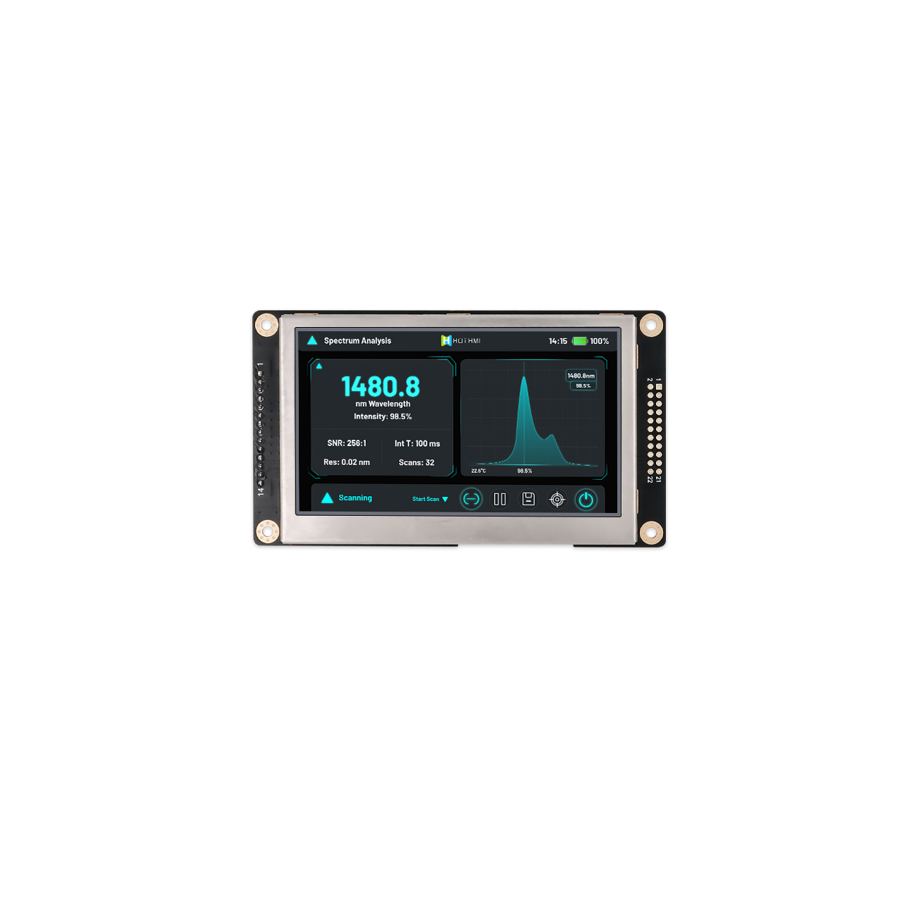
The HTM-H043A28-MCU&SPI-A01C is a 4.3-inch TFT LCD with a 480 × 272 resolution. It supports 8080 MCU and SPI interfaces. The module uses an NV3041 Driver IC, provides 900 cd/m² brightness and operates from -30°C to +80°C.
Key specifications:
- 4.3-inch TFT LCD
- 480 × 272 resolution
- 8080 MCU / SPI interface
- NV3041 Driver IC
- 900 cd/m² brightness
- -30°C to +80°C operating temperature
- Capacitive touch
For embedded systems using STM32 or other MCUs as the main controller, both the 8080 parallel interface and SPI interface can be evaluated with this module.
If the MCU provides an external memory interface such as FSMC or FMC, an 8080 MCU Display can be considered as one of the display connection options. SPI can be evaluated when MCU pin resources are limited.
TFT-H040A31WQINVKN22 — 4.0-inch Bar MCU Display
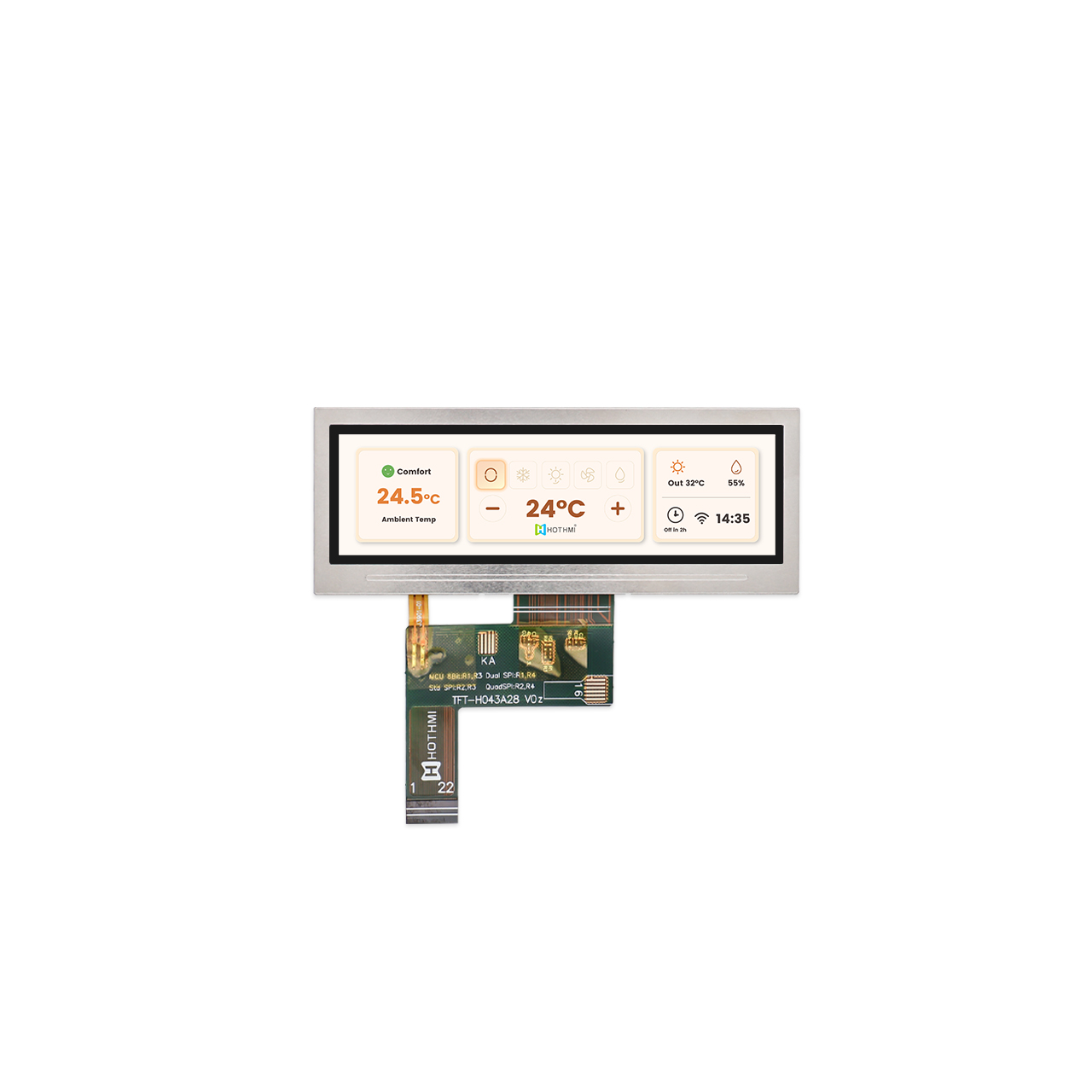
The TFT-H040A31WQINVKN22 is a 4.0-inch Bar Display with a 480 × 128 resolution. It supports SPI, QSPI and MCU interfaces. The module uses an NV3041A Driver IC, provides 1100 ± 150 cd/m² brightness and operates from -30°C to +85°C.
Key specifications:
- 4.0-inch Bar Display
- 480 × 128 resolution
- SPI / QSPI / MCU interface
- NV3041A Driver IC
- 1100 ± 150 cd/m² brightness
- -30°C to +85°C operating temperature
- Wide and narrow display form factor
This MCU Display is suitable for equipment with specific display-space requirements, including industrial instruments, control panels, equipment status displays and embedded information terminals.
Compared with a conventional 480 × 272 display, the 480 × 128 resolution requires less display data to be transferred for a full-screen update. It can also reduce some UI resource and Frame Buffer requirements. For equipment mainly displaying parameters, status information, numerical values and simple graphics, this Bar Display can be considered.
FAQ About MCU Display
Q1:What is an MCU Display?
An MCU Display generally refers to a display solution that uses an MCU interface such as 8080, 6800, or SPI to communicate with the main MCU through an LCD Driver IC.
Q2:Is an MCU Display suitable for STM32?
Yes. Compatibility depends on the specific STM32 model, available interfaces, RAM capacity, display resolution, and Driver IC. STM32 platforms with FSMC or FMC can be considered for 8080 MCU Display applications.
Q3:Is SPI better than an 8080 interface?
Neither interface is universally better.
SPI requires fewer signal lines and can work well for compact devices and UIs with relatively low data requirements. An 8080 parallel interface generally provides higher data throughput but requires more signal lines.
Q4:Does an MCU Display need a Frame Buffer?
Not always.
If the Driver IC has sufficient GRAM, the MCU can write display data to the Driver IC’s internal memory. Whether a Frame Buffer is required, and how much RAM is needed, depends on the GUI architecture and refresh method.
Q5:What resolution is suitable for an MCU Display?
The appropriate resolution depends on the UI requirements and available MCU resources. 240 × 320, 320 × 240, 480 × 272, and 480 × 800 can all be used in different embedded applications. Higher resolution generally increases display data and memory requirements.
Q6:Can an MCU Display have a touchscreen?
Yes. An MCU Display can be combined with either RTP or CTP. The LCD and touch interfaces can be designed independently. For example, the LCD can use an 8080 interface while the touch controller uses I²C.
Conclusion
MCU Display selection should be evaluated as part of the complete embedded system rather than as an isolated LCD specification.
Start by checking the MCU’s RAM, Flash, and available interfaces. Then calculate the Frame Buffer requirements and display data bandwidth for the target resolution. Driver IC, GRAM, color format, touch interface, brightness, operating temperature, and mechanical dimensions should also be reviewed before the display is finalized.
For low- to medium-resolution embedded UIs, 8080, 6800, and SPI interfaces remain practical options. The key is to match the display architecture with the capabilities of the MCU and the requirements of the application rather than selecting a display based on a single specification.
If the MCU model, target display size, and resolution have already been determined, HOTHMI can help match or customize a TFT LCD display solution according to the required interface, Driver IC, touch function, brightness, operating temperature, and mechanical specifications.