A Brief Overview of SPI Interface Applications in LCD and CTP Display Modules
There are various ways to connect a microcontroller (MCU), microprocessor (MPU), or central processing unit (CPU) to a liquid crystal display, among which the Serial Peripheral Interface (SPI Interface) is a common and efficient solution.
Fundamental Concept (I): Characteristics of LCD Driving Signals
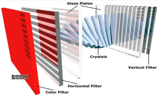
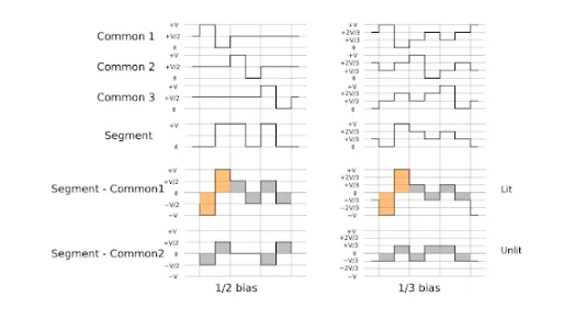
Liquid crystal display devices have specific requirements for driving signals—DC voltage is not permitted; instead, an alternating current (AC) waveform must be used, and the net current flowing through the liquid crystal material during operation must remain zero. Failure to comply with this principle will cause the liquid crystal material to gradually degrade or even suffer permanent damage over prolonged use.
Fundamental Concept (II): LCD Control and Driving Architecture
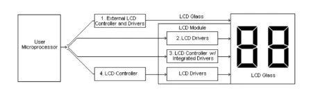
In a liquid crystal display driving system, driver integrated circuits are primarily divided into two categories: common drivers and segment drivers. Common drivers are responsible for generating row-scanning signals to select display rows or groups of rows, while segment drivers produce column-oriented signals to form characters or graphic pixels.
The controller IC receives display data in ASCII or JIS encoding from the host side and temporarily stores it in its built-in RAM. This data is then converted into serial dot-matrix patterns and transmitted to the LCD driver IC for output.
In graphic display modules, the driver/controller chip often plays a central role. On one hand, it receives display data from the microprocessor and stores it in RAM; on the other hand, it directly responds to control commands issued by the microprocessor, coordinating the timing between the common drivers and segment drivers.
Detailed Explanation of the SPI Interface
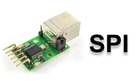
The SPI Interface is a synchronous serial communication protocol, typically consisting of four signal lines:
- SCLK: Serial Clock line, generated and output by the master device;
- MOSI: Master Output, Slave Input line, used for data transmission from the master to the slave device;
- MISO: Master Input, Slave Output line, used for returning data from the slave device to the master;
- SS: Slave Select line, used by the master to activate a specific slave device for communication.
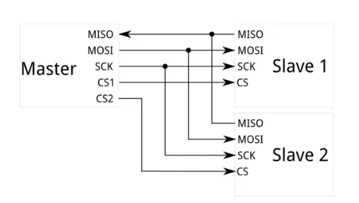
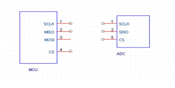
This interface supports full-duplex communication, meaning data can be transmitted and received simultaneously during the same clock cycle. It also offers relatively high data transfer rates, making it suitable for moderate data-volume scenarios. Additionally, SPI supports multi-slave connections, where the master device can select different slaves via individual SS pins, enabling bus multiplexing.
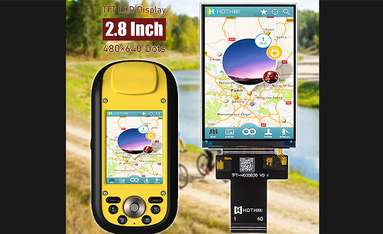
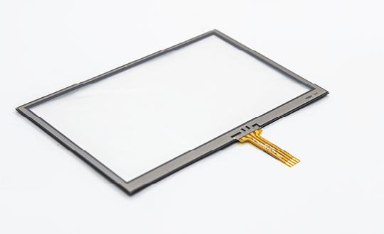
In practical display applications, the SPI interface is widely used for monochrome digital panels, character-type LCDs, graphic dot-matrix LCDs, small-sized TFT color displays, and the communication and control of certain capacitive touch panels. Its low pin count and simple wiring make it particularly suitable for portable devices with limited PCB space or strict power consumption requirements. Furthermore, some advanced SPI controllers support DMA transfers and interrupt mechanisms, which can further offload the main CPU and improve overall system response efficiency.
In summary, the SPI interface, with its straightforward hardware architecture, good scalability, and moderate transmission performance, has become one of the commonly adopted interconnection choices between small- and medium-sized display modules and host controller chips.