Description
128×64 lcd display Datasheet & Product Introduction
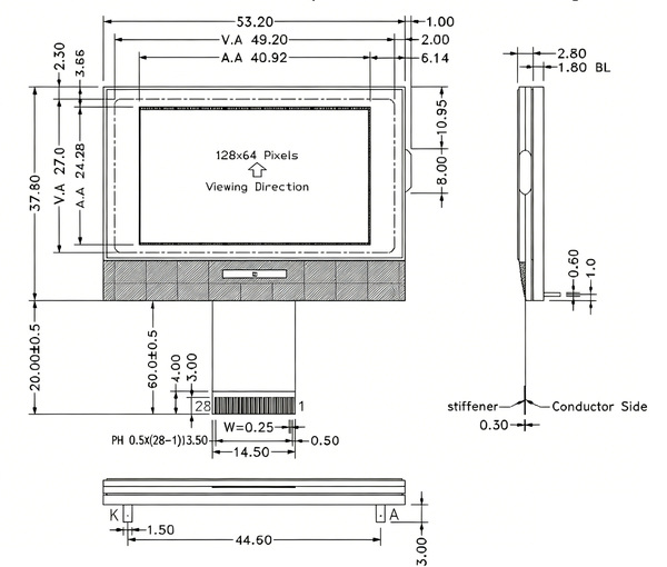
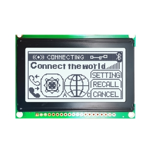
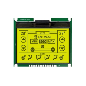
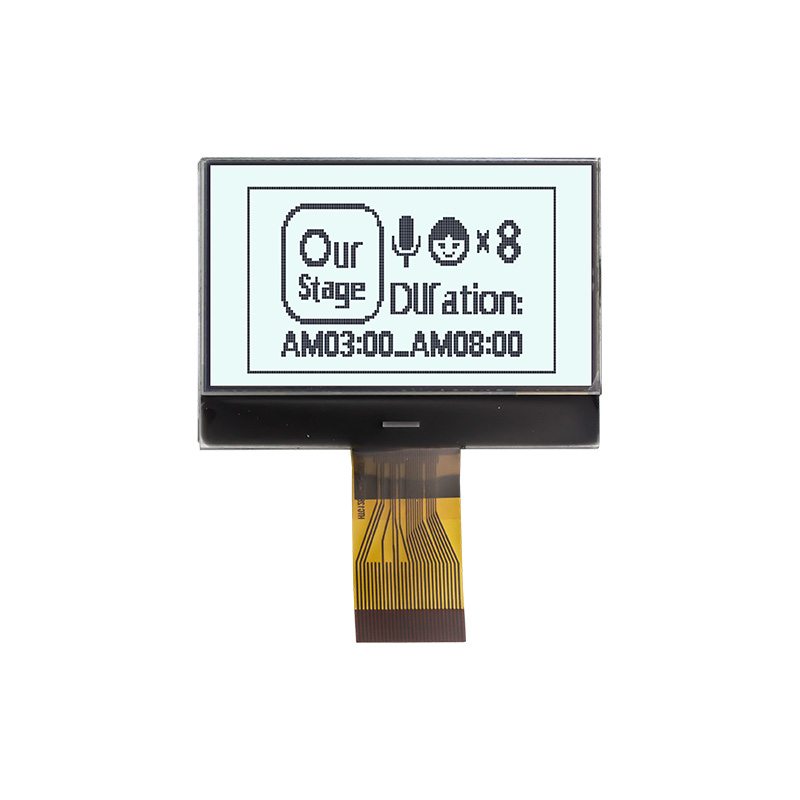
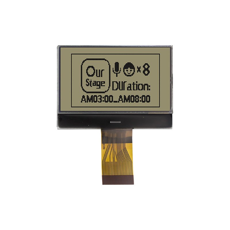
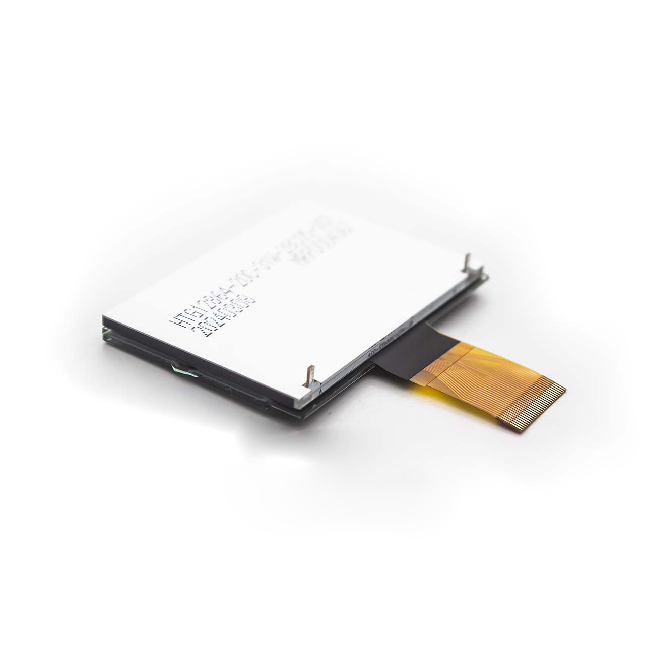
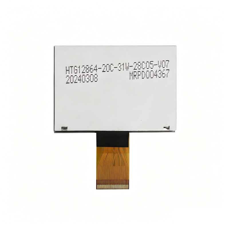
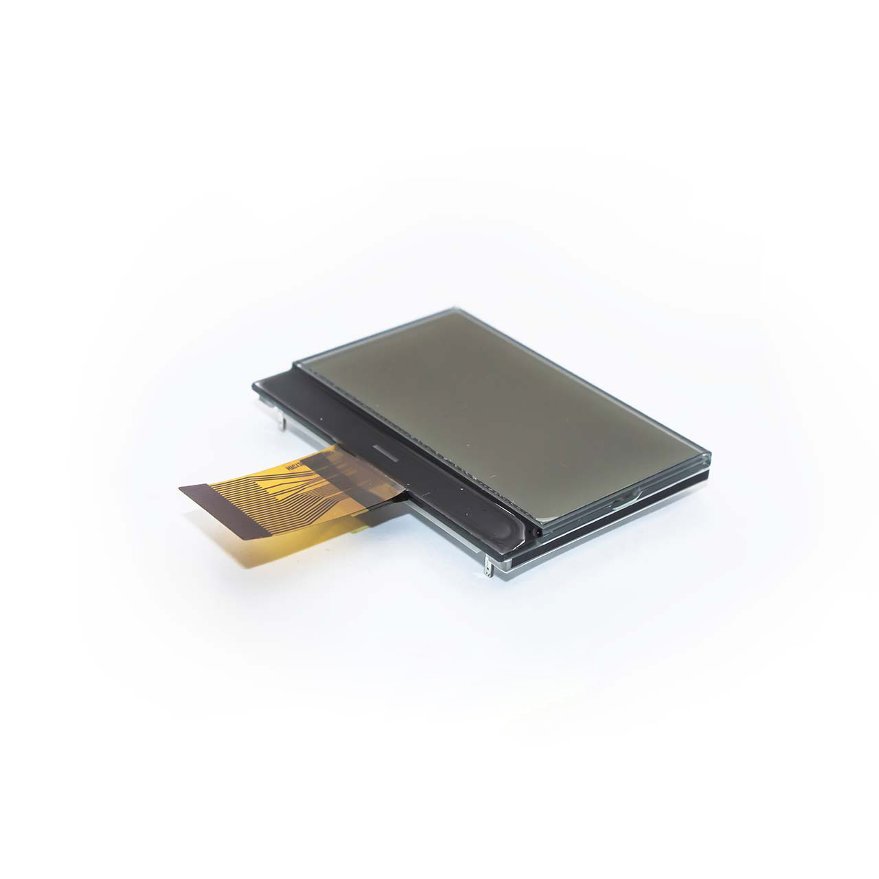
Product Overview The 128×64 lcd display graphic liquid crystal display module (Model: HTG12864-20C-31W) manufactured by HOTHMI is a highly reliable monochrome display solution. It features a 128×64 pixel resolution, adopts an FSTN transflective positive display mode, and delivers excellent outdoor visibility. Equipped with the high-performance ST7567 driver IC, this 128×64 lcd display module supports 1/64 duty and 1/9 bias drive, providing a clear 6 o’clock (6H) viewing angle.
Physical & Electrical Characteristics
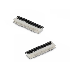
This compact 128×64 lcd display module measures 53.20 x 37.80 mm with a thickness of only 2.80 mm, making it ideal for portable devices. It uses a 28-pin FPC interface with 0.5mm pitch, supporting switchable parallel or serial communication. The module operates at a standard voltage of 3.3V and integrates a white LED backlight (3.1V/45mA operating parameters).
Environmental Adaptability
The 128×64 lcd display is RoHS compliant and features strong environmental tolerance. It has an operating temperature range of -20°C to +70°C and a storage temperature range of -30°C to +80°C, suitable for most industrial and consumer electronic applications.
Circuit Diagram
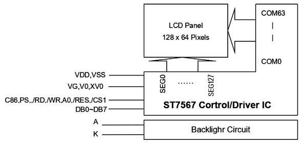
The system block diagram illustrates the internal logic architecture of the 128×64 lcd display, with the ST7567 driver chip as the core. As the central control unit, the chip communicates with an external MCU via an 8-bit parallel/serial bus (DB0-DB7) and control signals including chip select, reset, read and write. It directly drives the 128×64 pixel LCD panel through 128 segment lines (SEG) and 64 common lines (COM). The module also includes voltage pins (VDD, VSS, V0, etc.) for logic and drive power supply, as well as an independent backlight circuit controlled by anode (A) and cathode (K) pins, forming a complete display control system.
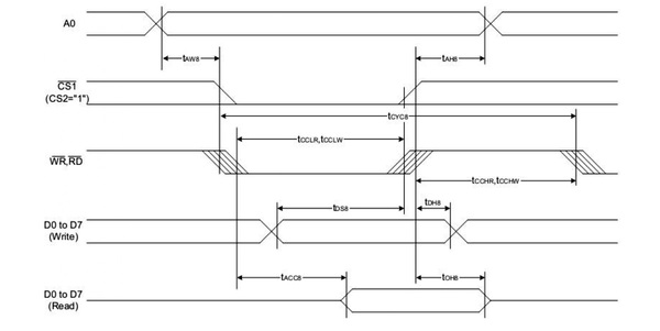
Data Transfer Specifications for the LCD Module in 8080-Series Parallel Interface Mode
This timing diagram illustrates the data transfer protocols for the LCD module operating in 8080-series parallel interface mode. Within a complete system cycle (tCYC8), the MCU must first establish a stable address signal (A0), followed by asserting the chip select signal (/CS1) low to enable the module. Subsequently, a logic level transition is initiated on the read/write control lines (/RD or /WR) to trigger the bus operation.
The diagram explicitly defines the Data Setup Time (tDS8) for write operations, requiring that data on the bus (D0-D7) remains stable before the control signal returns to a high level. For read operations, it specifies the Access Time (tACC8), which is the propagation delay from the instruction trigger until valid data appears on the bus. Strict adherence to these nanosecond-scale timing constraints is essential to ensure the accurate execution of display commands by the MCU and to prevent issues such as graphical artifacts (screen garbling) or system unresponsiveness.
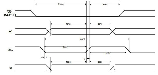
Data Transfer Specifications for the LCD Module in 4-Line Serial Interface (SPI) Mode
Technical Q&A about 128×64 lcd display
Q1: Does this 128×64 lcd display module support 5V MCU systems?
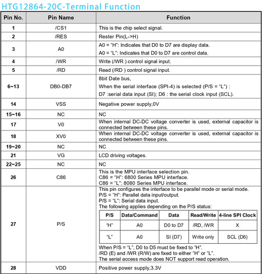
A: The module’s logic power supply (VDD) is rated at 3.3V. For 5V MCUs, it is recommended to connect current-limiting resistors of approximately 1K ohms in series on data and control lines (such as CS, A0, SCL, SI), or use a level shifter chip to avoid damaging the input terminals of the ST7567 driver IC due to high voltage.
Q2: How to switch between serial (SPI) and parallel modes via code?
A: Mode switching is determined by hardware pin levels. Per the schematic:
Parallel mode: Connect Pin 27 (P/S) to high level (H).
Serial mode: Connect Pin 27 (P/S) to low level (L). In serial mode, DB7 functions as serial data input (SI) and DB6 functions as serial clock (SCL).
Q3: What are the core advantages of FSTN transflective mode compared to standard STN mode?
A: Standard STN displays rely on backlighting and are barely visible in sunlight. The FSTN transflective mode of this 128×64 lcd display integrates a special compensation film and reflective layer. It uses the white LED backlight for indoor display and reflects natural sunlight for clear visibility outdoors. It is a cost-effective solution to the problem of unreadable displays in sunlight for outdoor instruments and charging piles.