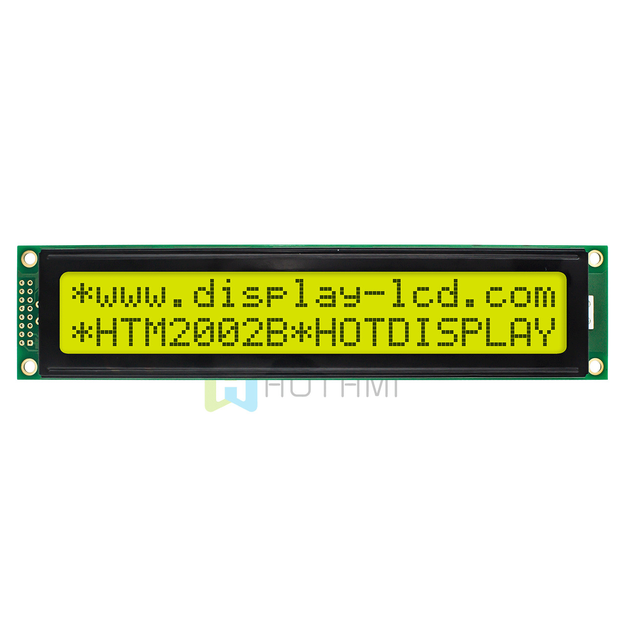
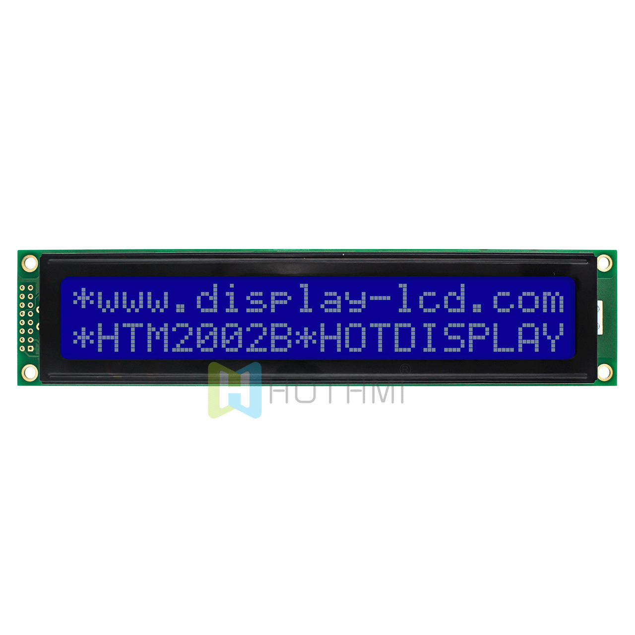
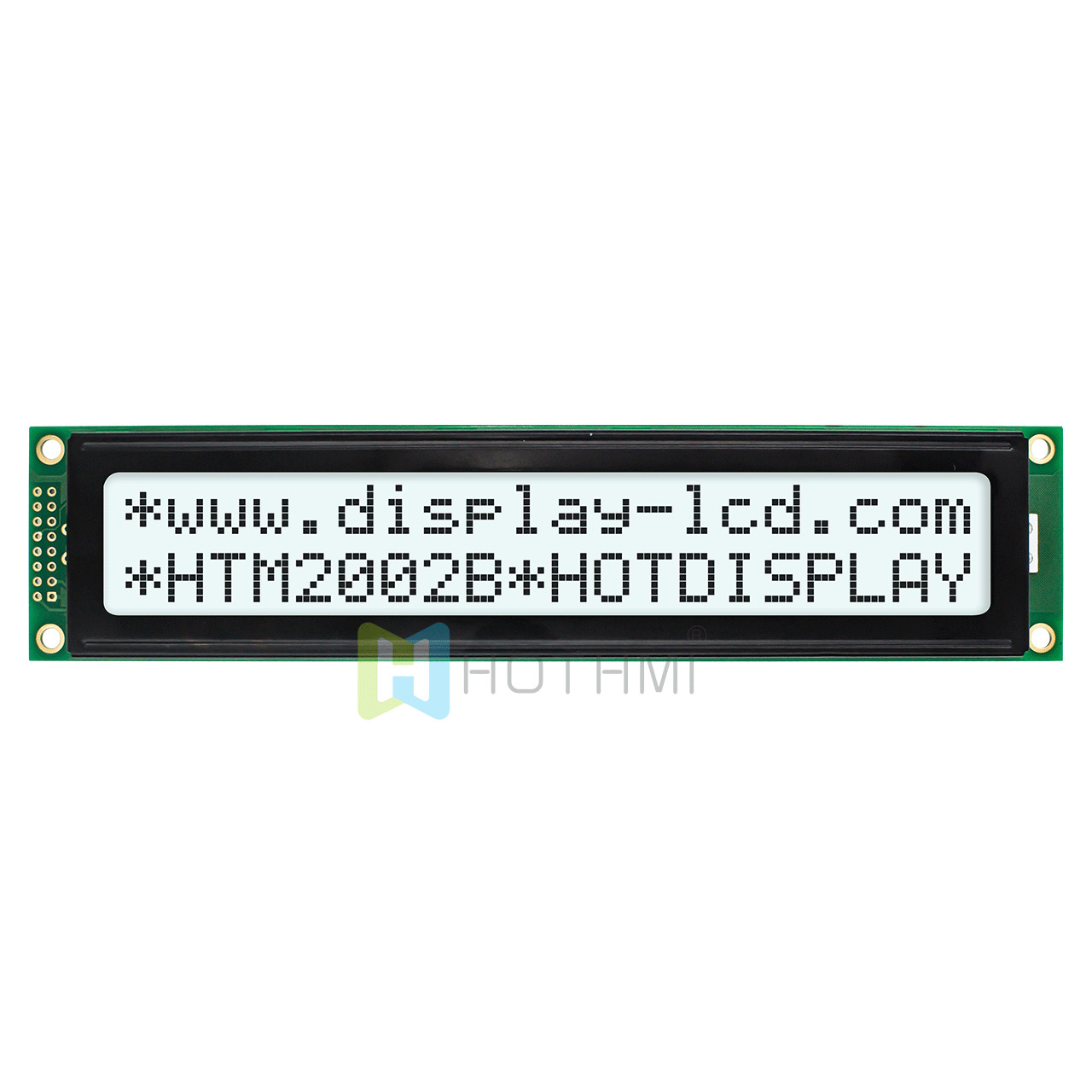
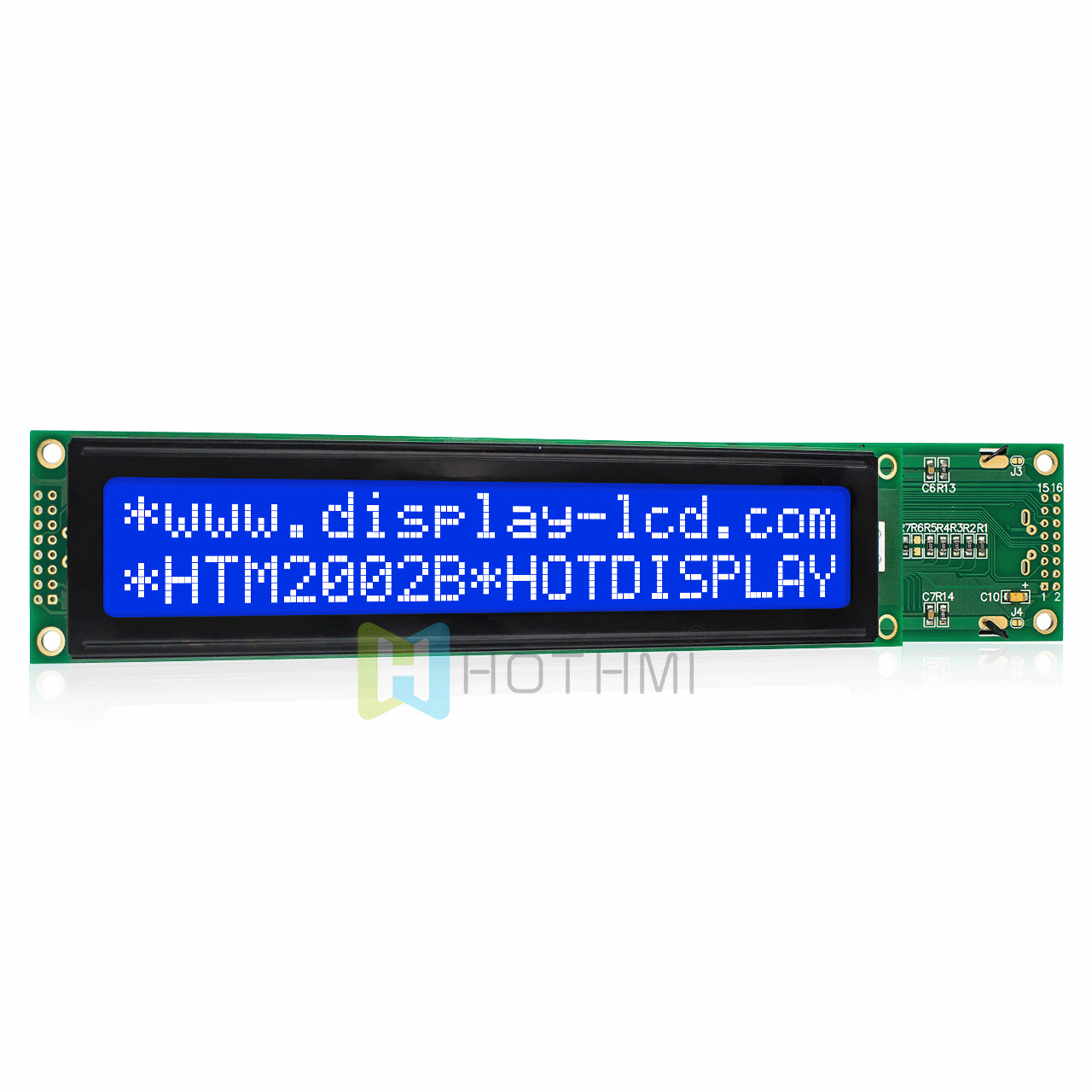
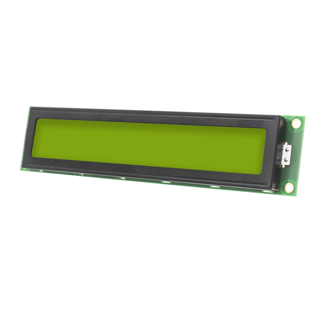
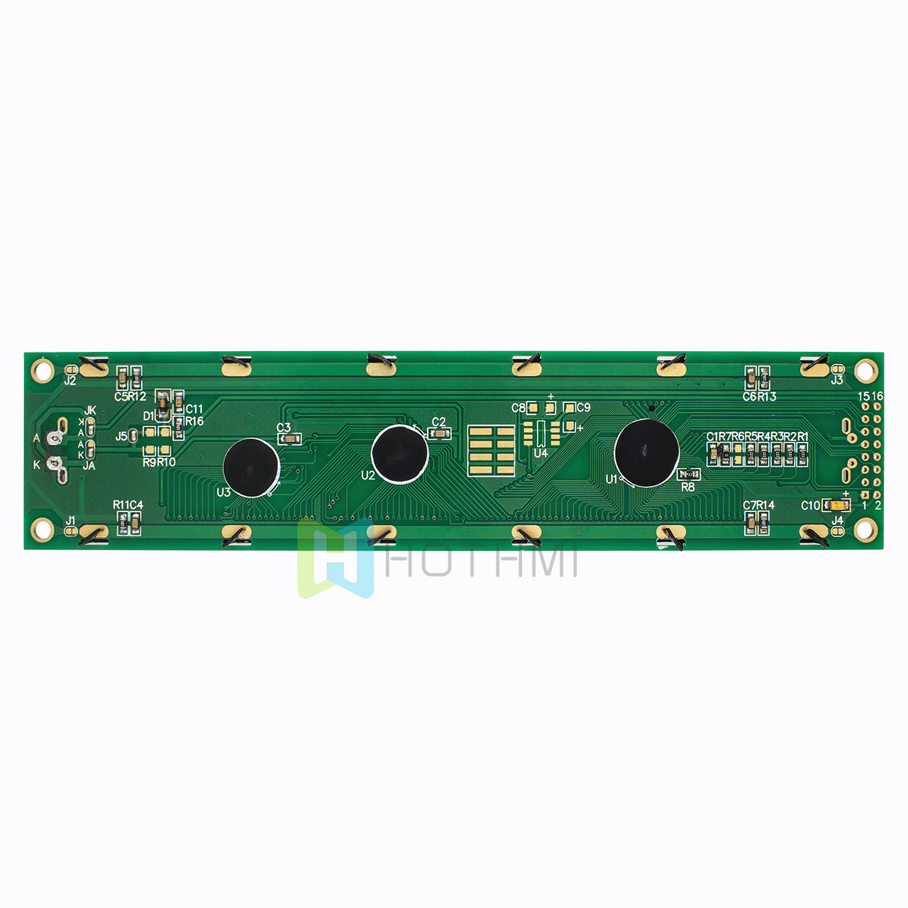
20×2 LCD Display Monochrome Module STN Yellow ST7066U
- Model: HTM2002B-01Y-A5P
- Type: 20×2 Character LCD Module
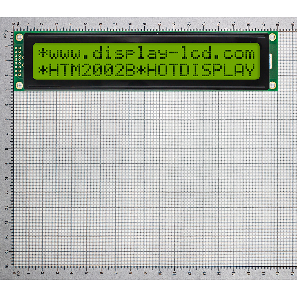
- Overall dimensions (mm): 180.0×40.0x11.0
- VA size (mm): 149.0×23.0
- Working temperature: -10℃~+60℃
- Supply voltage: 5.0V
- Driver chip:ST7066U
$38.00
In stock
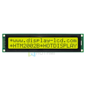
This item: 20x2 LCD Display Monochrome Module STN Yellow ST7066U
$38.00
$38.00
Description
Product Overview and Core Features of 20×2 LCD Display
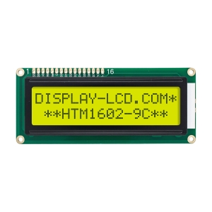
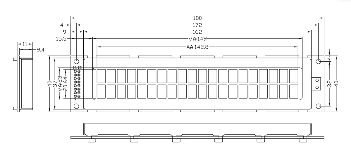
The HOTHMI HTM2002B is a 20×2 LCD Display (20 chars/line × 2 lines) featuring yellow-green STN positive transflective technology – black characters on a yellow-green background for excellent readability in any light: clear indoors with backlight and readable in direct sunlight via reflected light (no white-out). It integrates ST7066U (or equivalent) controller, 1/16 duty, 1/5 bias, 5.0V operation, 6 o’clock viewing direction, compact LED yellow backlight, dimensions 180×40×11mm (15.5mm max), visual area 149×23mm, standard 16-pin interface (VSS, VDD, VO, RS, R/W, E, DB0-DB7, A/K), operating temperature -10°C to +60°C (storage -20°C to +70°C). Ideal for industrial control, instrumentation, and embedded devices.
- Mainstream Controller IC, Mature Ecosystem: The 20×2 LCD Display module integrates ST7066U or industry-standard equivalent compatible controller IC. This means its underlying instruction set is fully compatible with all mainstream open-source libraries.
- Optimal Viewing Angle & Superior Contrast: The product features a 6 o’clock optimal viewing direction design, perfectly matching the upward or direct viewing angles of most instrument panels or equipment surfaces. With precise 1/16 duty cycle and 1/5 bias ratio, it ensures sharp character edges without blurring or ghosting, maintaining high contrast even with continuous long-term display.
- Ultra-Slim & Robust Physical Structure: The module’s overall dimensions are 180mm × 40mm, with thickness controlled between 11.0mm and 15.5mm (including the maximum thickness of the bottom LED backlight). The visual area reaches 149mm × 23mm. Character LCD Displays are generously sized with precisely calibrated dot pitch spacing and shock-resistant construction, facilitating easy assembly in compact equipment enclosures.
- Industrial-Grade Wide Temperature Durability: Specially optimized for harsh industrial environments, the standard operating temperature spans -10°C to +60°C, with storage temperature supporting -20°C to +70°C. Whether used in substations, outdoor cabinets, vehicle-mounted equipment, or hot factory workshops, it ensures stable 24/7 operation without failure.
Pin Description and Interface Definition of 20×2 LCD Display
To facilitate rapid circuit schematic and PCB design, this 20×2 LCD Display module uses the industry-standard 16-pin single-row pin header interface with 2.54mm pin spacing. The detailed function and electrical definitions of the 16 pins are as follows:

Wiring Guide and Operating Modes of 20×2 LCD Display
In actual hardware development, this 20×2 LCD Display supports both 8-bit and 4-bit parallel modes.
8-bit Parallel Wiring (Full-Speed Mode)
- Power and Backlight: Pin1 (VSS) → GND; Pin2 (VDD) → 5V; Pin15 (A) → 5V via 10–100Ω resistor; Pin16 (K) → GND.
- Contrast: 10K pot between 5V and GND, wiper to Pin3 (VO).
- Control: Pin4 (RS) & Pin6 (E) to GPIO; Pin5 (R/W) → GND (write-only).
- Data: Pin7–14 (DB0–DB7) to an 8-bit port.
- Use: High-speed, pin-rich systems.
4-bit Parallel Wiring
- Wiring: Power, contrast, control same as 8-bit. Data: DB0–DB3 (Pin7–10) unconnected; only DB4–DB7 (Pin11–14) to 4 GPIO pins.
- How it works: Each byte sent as high 4 bits then low 4 bits over same 4 lines, each followed by an E pulse to latch.
- Trade-off: Saves 4 I/O pins; speed halved but fine for text display.
Backlight Design and Optical Specifications
The HTM2002B features high-brightness side/bottom LED solid-state backlight with strictly screened emission wavelength presenting a pure, soft yellow-green color.
- Human Factors Engineering Advantage: The yellow-green background with black characters is among the least fatiguing color combinations for human vision. Whether operators monitor data for extended periods or glance briefly, text remains highly visible and comfortable to read.
- Long Life and Vibration Resistance: Compared to older CCFL backlights, LED solid-state backlight contains no high-voltage components and offers excellent vibration and shock resistance. Backlight life typically exceeds 50,000 hours.
- Intelligent Power Control: Under standard 5.0V drive, backlight current consumption is very low. Engineers can connect Pin 15 (A) to a PWM-capable microcontroller pin, and by dynamically adjusting the PWM duty cycle via software, easily achieve multi-level backlight brightness adjustment – automatically dimming at night and brightening during the day – significantly reducing overall power consumption of the embedded terminal.
Typical Applications of 20×2 LCD Display
Thanks to its high system stability, extremely low failure rate, and highly standardized instruction architecture, this 20×2 LCD Display module has become deeply embedded in numerous professional and consumer hardware fields:
- Industrial Control and Automation Panels: PLC peripheral display units, CNC machine status windows, VFD parameter configuration panels, equipment room environmental monitoring displays.
- Smart Electronic Instruments: High-precision digital multimeter displays, three-phase digital power meters, lab DC power supplies, industrial gas detectors, electronic weighing instruments.
- Commercial and Smart Logistics Terminals: Vehicle taximeter displays, vending machine user prompt screens, barcode scanner base stations, cafeteria payment terminals.
- Medical and Environmental Monitoring Equipment: Portable medical monitor parameter screens, small sterilizer control systems, water quality analyzers.
- DIY Electronics and Educational Projects: Classic teaching equipment for Arduino, Raspberry Pi, STM32, ESP32, and other mainstream microcontroller development boards; widely used in university EE graduation projects and research.
Technical FAQ of 20×2 LCD Display
Q1: I’m using a 3.3V microcontroller. How do I safely and efficiently connect this 5V 20×2 LCD Display?
A: You can connect them directly by following these two key points:
- Direct Logic Connection:At 5V VDD, the LCD’s high-level input threshold is 2.2V–2.5V. Since 3.3V MCU outputs exceed 3.0V, the LCD recognizes them perfectly. Set MCU GPIOs to push-pull output for a direct connection without level shifters.
- Safe Write-Only Setup:Solder Pin 5 (R/W) directly to GND. This locks the LCD in “write-only” mode, preventing any 5V back-feeding to protect your 3.3V MCU. Connect the module VDD and the contrast potentiometer to 5V.
Q2: What are the timing and delay requirements for the Enable (E) pin pulse in 4-bit mode?
A: The E pin acts as a data latch clock. Follow these strict timing rules:
- Pulse Sequence:Set RS and R/W levels -> output 4-bit data -> pull E high (hold for 1–2µs to meet the 150ns setup time) -> pull E low (falling edge latches data).
- Execution Delays:Standard commands (writing characters, setting cursor) take 40µs–100µs. Special commands like “Clear Screen” or “Return Home” require a much longer delay of 1.5ms–3ms before sending the next instruction.
Additional information
| Weight | 0.2 kg |
|---|
Attributes
| Item | Specification Connent | Unit |
| Name | HTM2002B | |
| Number of dots | 20x2 Character | dots |
| Module size | 180.0 × 40.0 × 11.0 (MAX) | mm |
| VA size | 149.0(W) × 23.0(H) | mm |
| AA size | 142.8(W) × 20.6(H) | mm |
| Pixel pitch | 1.22 × 1.22 | mm |
| IC | ST7066U | |
| voltage | 5.0V | V |
| backlight | White Backlight | |
| display mode | FSTN+ | |
| Drive mode (Duty) | —— | |
| type | Character Module | |
| characteristic | Transflective Polarizer |
Related products