

Description
Product Overview and Core Highlights of the SPI TFT Display
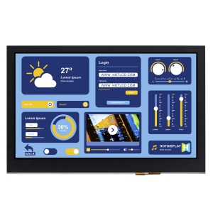
This is a 5.0-inch SPI TFT Display with a resolution of 480(RGB)×272 pixels and an active display area of 110.88 mm (horizontal) × 62.832 mm (vertical). In terms of module dimensions, the pure TFT version measures 120.70 mm (horizontal) × 75.80 mm (vertical) × 2.90 mm (thickness), while the version with a capacitive touch panel (CTP) has a thickness of 4.70 mm.
The SPI TFT Display module offers a viewing direction of U85/D85/R85/L85, supporting full-angle display. For interfaces, it defaults to an 8-bit 8080-series MCU parallel interface and is also compatible with 3-wire or 4-wire standard SPI interfaces. The TFT driver IC is NV3041, and the optional capacitive touch panel driver IC is FT5216. Touch screen options include no touch, capacitive touch.
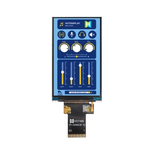
Capacitive touch version:

None touch version:
Core Highlights of the SPI TFT Display
- Full-viewing-angle IPS panel: Maintains excellent color accuracy and contrast (typical contrast ratio of 1000:1) from any angle.
- Flexible multi-interface configuration: Natively supports 8-bit MCU parallel interface (default), standard 3-wire/4-wire SPI interfaces, and dual/quad Quad SPI interfaces. This makes the module perform exceptionally well in SPI TFT display applications requiring minimal pins.
- Ultra-high brightness: The non-touch version achieves a brightness of 1000 cd/m², remaining clearly visible in strong light or semi-outdoor environments. The capacitive touch (CTP) version still delivers 800 cd/m².
- Industrial-grade wide temperature design: Operating temperature ranges from -30°C to +80°C, with storage temperature from -40°C to +90°C, easily handling harsh industrial deployment environments.
- High-reliability driver chips: The TFT section is powered by the stable NV3041 driver IC, while the optional touch screen uses the FT5216 capacitive touch driver IC, both mature technologies.
Pin Description and Hardware Wiring Guide
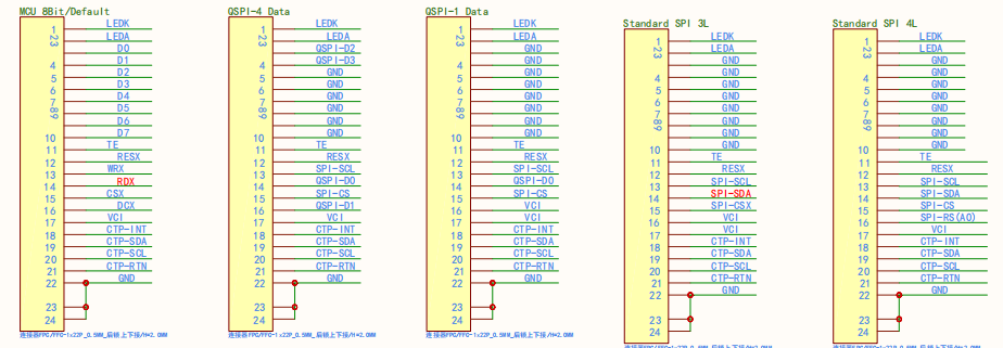
The SPI TFT Display routes all control signals through a 22-pin FPC physical interface. For development convenience, the official design integrates TFT drive, backlight, and touch screen pins into one connector.
Module Pin Definition List (22-Pin Definitions)

Interface Circuit Switching and Physical Wiring Instructions
A key feature of the TFT-H050A19 is the ability to physically switch interface modes by adjusting on-board resistor positions on the FPC. For projects requiring an SPI TFT display, refer to the following resistor configurations:
Default 8-Bit MCU Parallel Interface
- Resistor state: R1 soldered.
- Wiring method: Requires connection of data lines DB0 to DB7 from the host controller (e.g., STM32/FSMC), plus control lines such as CSX, DCX, WRX, and RDX.
Standard 3-Wire / 4-Wire SPI Interface (Standard SPI)
- Resistor state: R2 soldered.
- Wiring method (using 4-wire SPI as an example):
- Host SPI_CS connects to module CSX.
- Host SPI_SCLK connects to module WRX (as serial clock).
- Host SPI_MOSI connects to module RDX (as serial data input).
- Host GPIO output connects to module DCX (for data/command switching).
- This mode greatly reduces the host’s I/O pin usage, making it ideal for various low-power and pin-constrained MCU platforms.
Quad SPI Interface (Quad SPI / QSPI)
- Resistor state: R2 and R4 soldered.
- Wiring method: Data lines expand to QSPI-D0, QSPI-D1, QSPI-D2, QSPI-D3. When paired with a host MCU that supports QSPI hardware acceleration (such as high-end microcontrollers or Linux system-on-modules), this achieves high-speed screen updates with very few pins, overcoming the throughput bottleneck of traditional SPI.
Note: For the capacitive touch panel (CTP), the I2C signals (TP-SDA, TP-SCL) must have pull-up resistors on the main board, with a recommended resistance of 2KΩ to 4.7KΩ. The power supply should be 3.0V to 3.3V.

SPI TFT Display Backlight and Electrical Characteristics Design
To ensure reliable display operation in various challenging lighting environments, this module is equipped with a high-performance, high-brightness white LED backlight assembly.
- Backlight driving conditions: Constant current drive type. Typical forward voltage VF = 18.0V ± 1.0V, typical forward current IF = 40mA.
- LED lifetime: When continuously lit at room temperature (25 ± 3°C), backlight life reaches 20,000 to 30,000 hours (defined as brightness decline to 50% of initial value).
- Recommended backlight control circuit: It is strongly recommended to include a dedicated backlight driver IC in the peripheral circuit, such as the LP3352 or similar high-voltage boost LED driver IC. The host controller can output a PWM signal to the EN/PWM pin of the driver IC. The recommended PWM dimming frequency is 25KHz (supporting adjustment from 100Hz to 30KHz) to effectively avoid backlight flicker and achieve smooth dimming.


Target Applications
Thanks to the convenience of the high-speed SPI TFT display interface, industrial-grade wide-temperature performance, and high sunlight-readable brightness of up to 1000 nits, the TFT-H050A19 series is widely suitable for:
- Industrial automation and intelligent hardware: PLC HMI interfaces, EV charging station displays, high-end test instruments. The wide temperature range and ESD protection ensure high stability in harsh conditions.
- IoT and smart home control hubs: Smart home control panels in villas, high-end appliance displays. Combined with the optional FT5216 capacitive touch screen, it provides a smooth touch UI experience.
- Medical electronics terminals: Portable patient monitors, analyzer display panels. High contrast and full viewing angle IPS ensure medical staff can accurately read physiological data from any angle.
- Automotive dashboards and outdoor equipment: Motorcycle digital dashboards, high-end two-wheeler vehicle infotainment systems. Ultra-high brightness makes it resistant to direct outdoor sunlight.
Technical FAQ for SPI TFT Display
Q1: Why choose an SPI interface to drive a 5.0-inch SPI TFT Display? What are the disadvantages of traditional RGB or parallel interfaces?
A1: Traditional 5.0-inch 480×272 displays mostly use 24-bit RGB interfaces or 16-bit MCU parallel interfaces, requiring 20 to 30 I/O pins from the host controller. This is difficult for many smaller, pin-limited MCUs (such as some Cortex-M4/M7 microcontrollers). In contrast, using an SPI TFT display, especially with Quad SPI mode as supported here, requires only 4 to 6 pins for full-screen image data transmission. This not only significantly simplifies PCB routing and reduces the cost of multilayer boards but also frees up many host pins for other peripherals like sensors and wireless communication modules.
Q2: When using an SPI serial interface to drive a medium resolution of 480×272, can the frame rate be guaranteed? Will there be noticeable lag or tearing?
A2: With a traditional single-wire standard SPI interface, serial data bandwidth limitations may indeed cause difficulty when refreshing full-screen complex dynamic images. However, the TFT-H050A19 module’s built-in NV3041 driver IC natively supports Quad SPI mode. In QSPI mode, each clock cycle can transmit 4 bits of data in parallel, instantly increasing data throughput to four times that of traditional SPI. Additionally, the module provides a TE (Tearing Effect) synchronization pin. By connecting the TE pin to an external interrupt on the host, the software can write the next frame of data during the vertical blanking interval of the screen’s internal frame memory refresh cycle, thus perfectly eliminating screen tearing and flickering at high refresh rates.
Q3: Are there strict requirements for the power-on reset timing when developing initialization code for this SPI TFT Display?
A3: Yes. The LCD module contains complex internal power charge pumps and register configurations. If the reset timing is incorrect, the driver chip (NV3041) may fail to correctly load factory calibration parameters from non-volatile memory (NVM), resulting in a white screen or abnormal display. According to the official low-level reference code, the standard power-on hardware reset operation must strictly follow the specified time delays.
If you have any further needs, please contact us.