
Description
Detailed Product Guide: HTG9664F Industrial 96×64 Dot Matrix COG Display
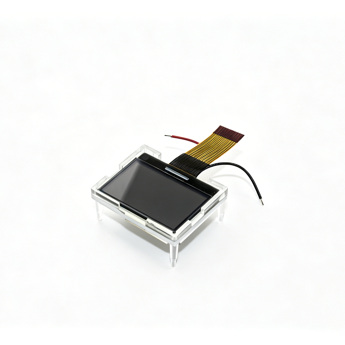
When designing embedded systems or smart hardware, selecting a display that balances power consumption, dimensions, and clarity is critical. The HTG9664F-31W-18C05, manufactured by HOTHMI, is a monochrome dot matrix COG Display specifically engineered for industrial-grade reliability. Utilizing Chip-on-Glass (COG) technology and a high-integration driver IC, it is the ideal choice for compact handheld devices.

Technical Specifications Overview
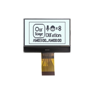
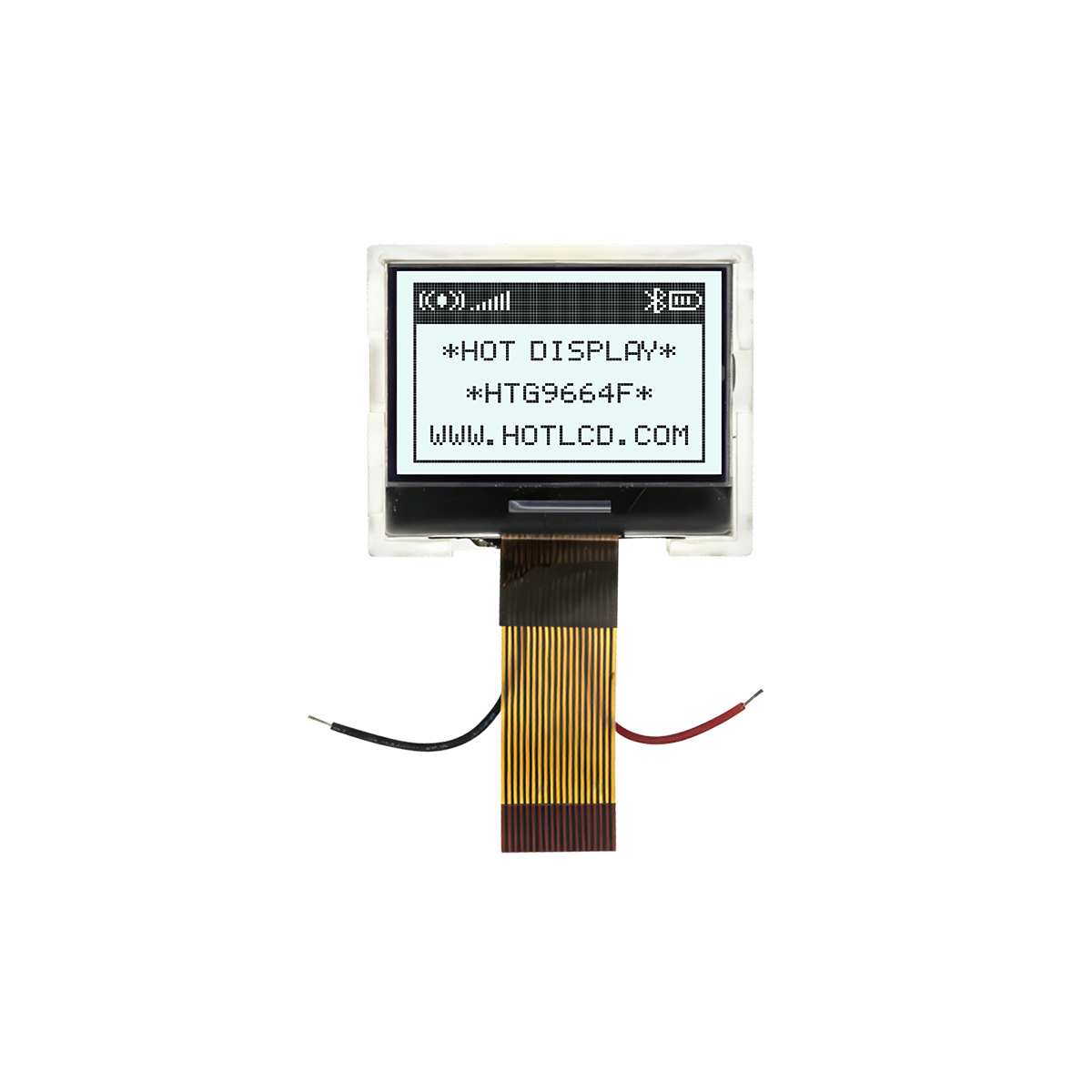
This module is a standard FSTN Positive mode liquid crystal display.
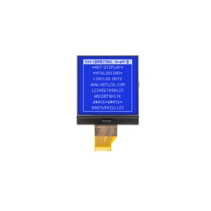
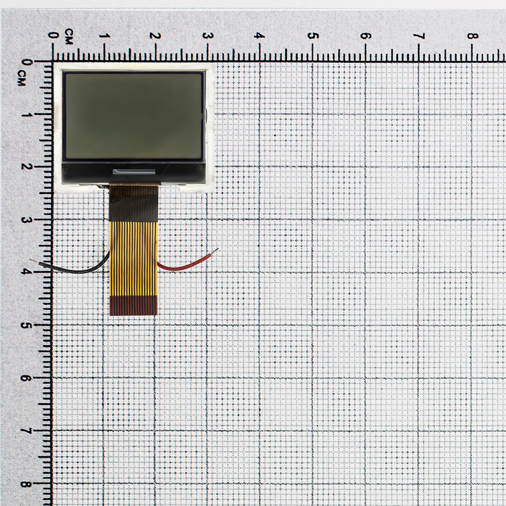
Resolution and Size: Featuring a 96×64 pixel array within a compact 31.0 x 25.4 mm outline, providing ample space for clear graphics and multi-line text.
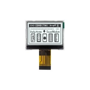
Display Technology: The FSTN (Film-compensated Super-twisted Nematic) technology provides higher contrast and wider viewing angles (6 o’clock direction) compared to traditional STN, ensuring data remains legible in complex environments.
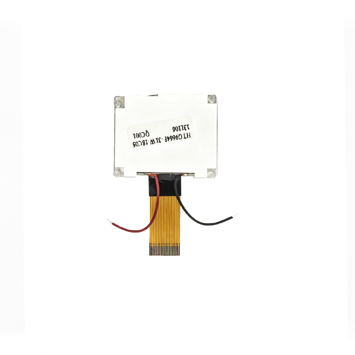
Integrated Driver: Powered by the ST7549R controller IC, which integrates a DC-DC voltage converter, regulator, and follower, significantly simplifying external hardware design.
Versatile Interfaces: Compatible with 8080/6800 parallel, 3-wire/4-wire SPI serial, and I2C interfaces to suit various MPU requirements.
Hardware Construction and Layer Analysis
To understand the durability of this COG Display, here is a detailed breakdown of its core structural components:
| Top Polarizer Layer (Upper Polarizer) | Filters polarized light and determines the 6H viewing direction and contrast. |
| Upper Glass Substrate (Ultra-thin Float Glass) | Carries the common electrode and protects the internal liquid crystal layer. |
| Liquid Crystal Layer (FSTN Liquid Crystal) | Responsible for the 96×64 dot matrix imaging with positive transflective display characteristics. |
| Lower Glass Substrate (Ultra-thin Float Glass) | Carries the segment/COM electrodes and ITO circuitry. |
| COG Driver Layer (ST7549R Die + ACF Conductive Film) | Directly bonded to the glass to handle pixel driving and interface communication. |
| Backlight Structure (LED Beads + Light Guide Plate + Reflector + Diffuser) | White LED backlight providing uniform light output for enhanced visibility in low-light conditions. |
| Bottom Protection (Protective Film / Shading Glue) | Provides insulation, dustproofing, scratch resistance, and anti-static protection. |

COG Display Key Industry Applications
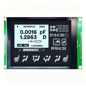
- Smart Industrial Instruments: Handheld thickness gauges and laser rangefinders. The 96×64 resolution is perfect for real-time waveforms and parameter grids.
- Medical Electronics: Portable glucose meters and pulse oximeters. FSTN contrast ensures legibility for elderly users in various lighting conditions.
- IoT Terminals: LoRa node configuration screens and smart gateway status displays.
Core Product Highlights
Ultra-Thin COG Technology
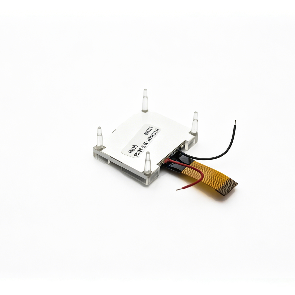
By using Chip-on-Glass (COG) technology to mount the driver IC directly onto the glass, the module size is minimized while vibration resistance is improved—a crucial factor for handheld equipment prone to drops or impact.
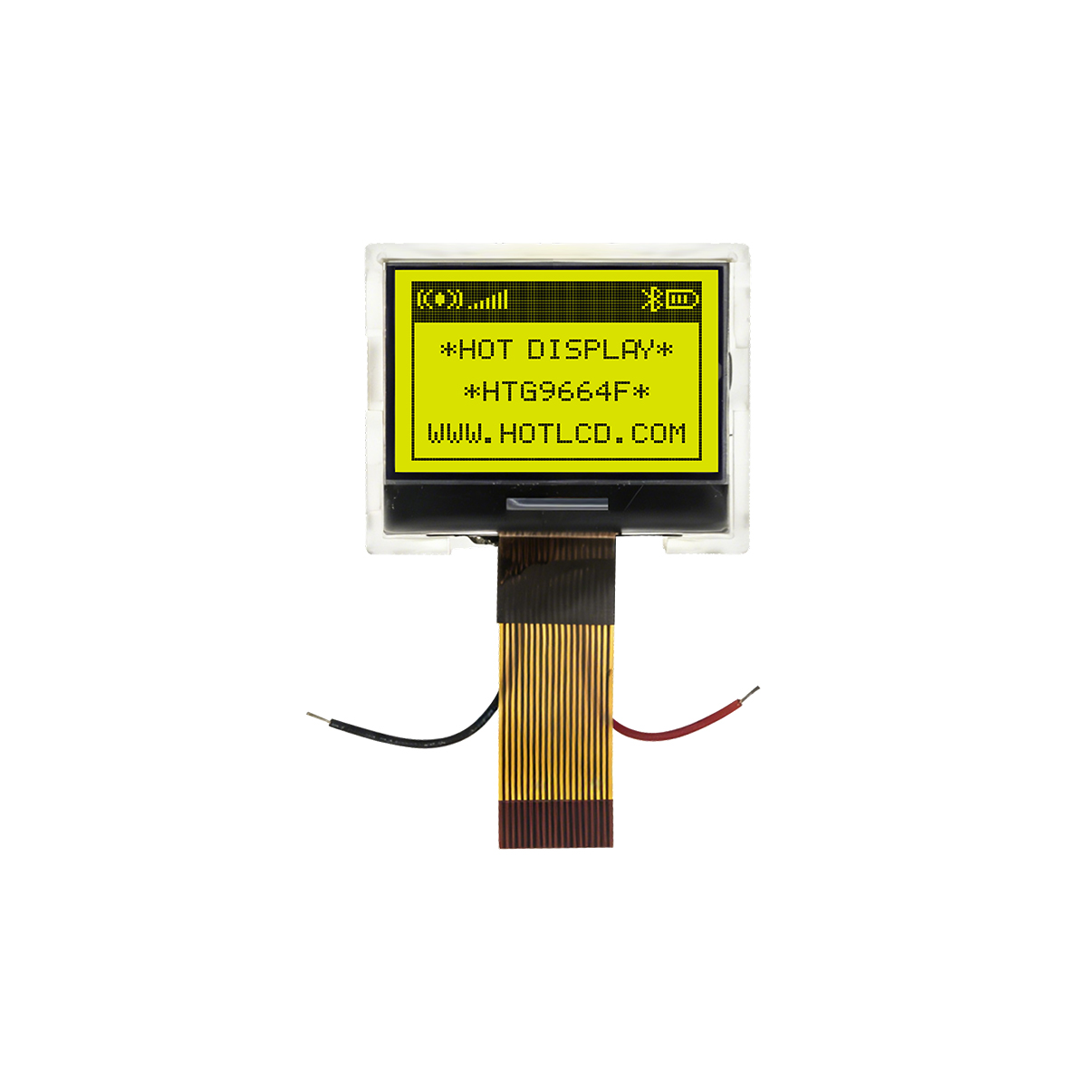
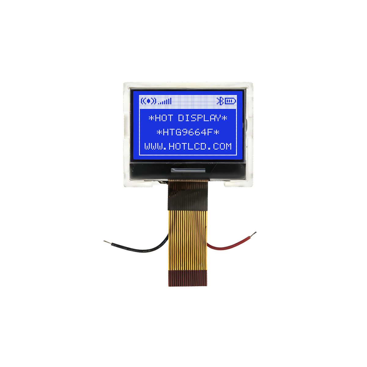
Flexible Power and Backlight Design
The operating voltage (VDD) ranges from 1.7V to 3.3V, making it perfect for battery-powered devices. The high-brightness white LED backlight draws only 30mA typically, balancing high visibility with long battery life.
FAQ: COG Display Technical Support
Q1: Is this screen readable under direct sunlight?
A: Yes. This module uses a Transflective mode. In bright light, it uses ambient light reflection for imaging; in dark environments, the white LED backlight provides clarity, ensuring low power consumption in all conditions.
Q2: Why set the COG Display LCD Bias to 1/9 during initialization?
A: This is the optimal bias ratio for 1/65 Duty driving. It maximizes the voltage difference between “on” and “off” pixels to achieve the highest possible contrast.
Q3: Which interface should I use if my MCU pins are limited?
A: We recommend the I2C or 3-line SPI interface. By configuring the PS1/PS2 pins, you can reduce the communication requirement to just 2 or 3 signal lines.
Q4: What is the function of the VOUT pin?
A: VOUT is the output of the internal booster circuit. When using the internal voltage generator, VLCDIN and VLCDOUT must be connected with an external capacitor to ground (VSS) to generate the necessary LCD driving voltage (up to 13V).
Reliable COG Display LCD Supplier from China—Sample Acceptable
HOTHMI focuses on the COG Display LCD field and can customize various LCD displays to meet diverse product needs. It supports personalized adjustments to size, resolution, interface, backlight, structure, and multi-layer installation methods, providing one-stop display solutions for industrial, handheld devices, smart home, and other scenarios.