Structure and Composition of Four-Wire Resistive Touch Screens
Resistive touch technology is widely adopted in many color display applications. Depending on the number of lead wires, resistive touch screens can be classified into four-wire, five-wire, and six-wire variants, among which the four-wire type is the most commonly used. This article provides a detailed analysis of its structural design and constituent materials.
General Construction of Resistive Touch Screens
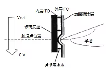
A resistive touch screen is essentially a resistive film layer closely bonded to the surface of a display panel, constructed from multiple laminated composite films. Its basic architecture includes a lower substrate made of glass or acrylic, with its upper surface coated with a transparent ITO (indium tin oxide) conductive layer. Over this lower substrate lies an upper sheet—either a plastic film or a thin glass plate—whose underside is also coated with an ITO conductive layer. The outer (top) surface of this upper sheet is hardened to provide a smooth, scratch-resistant finish. Between the two conductive layers, numerous tiny transparent insulating spacer dots are evenly distributed to keep the layers separated when no pressure is applied. When a finger presses on the screen, the two conductive layers make contact precisely at the touch point. Both ITO working layers must remain intact and continuous. Along each side edge of the two working surfaces, silver conductive paste is applied as electrode strips. By applying 5V to one end and 0V to the opposite end, a uniform and linear voltage gradient is established across each working surface.
Specific Structure of Four-Wire Resistive Touch Screens
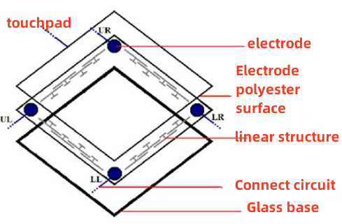
The four-wire resistive touch screen represents an early generation of resistive technology. Its structure consists of an upper diaphragm (approximately 0.2 mm thick, made of glass or plastic film) and a lower substrate (0.7 to 1.1 mm thick, typically glass). The inner surfaces of both layers are coated with ITO film, which serves as a uniform resistive layer with a sheet resistance ranging from about 200~300/port. On the lower substrate, the ITO layer is processed using photolithography to create dense, uniformly arranged micro-bumps. These bumps divide the ITO layer into numerous small isolated zones, which helps enhance the touch screen’s resolution accuracy.
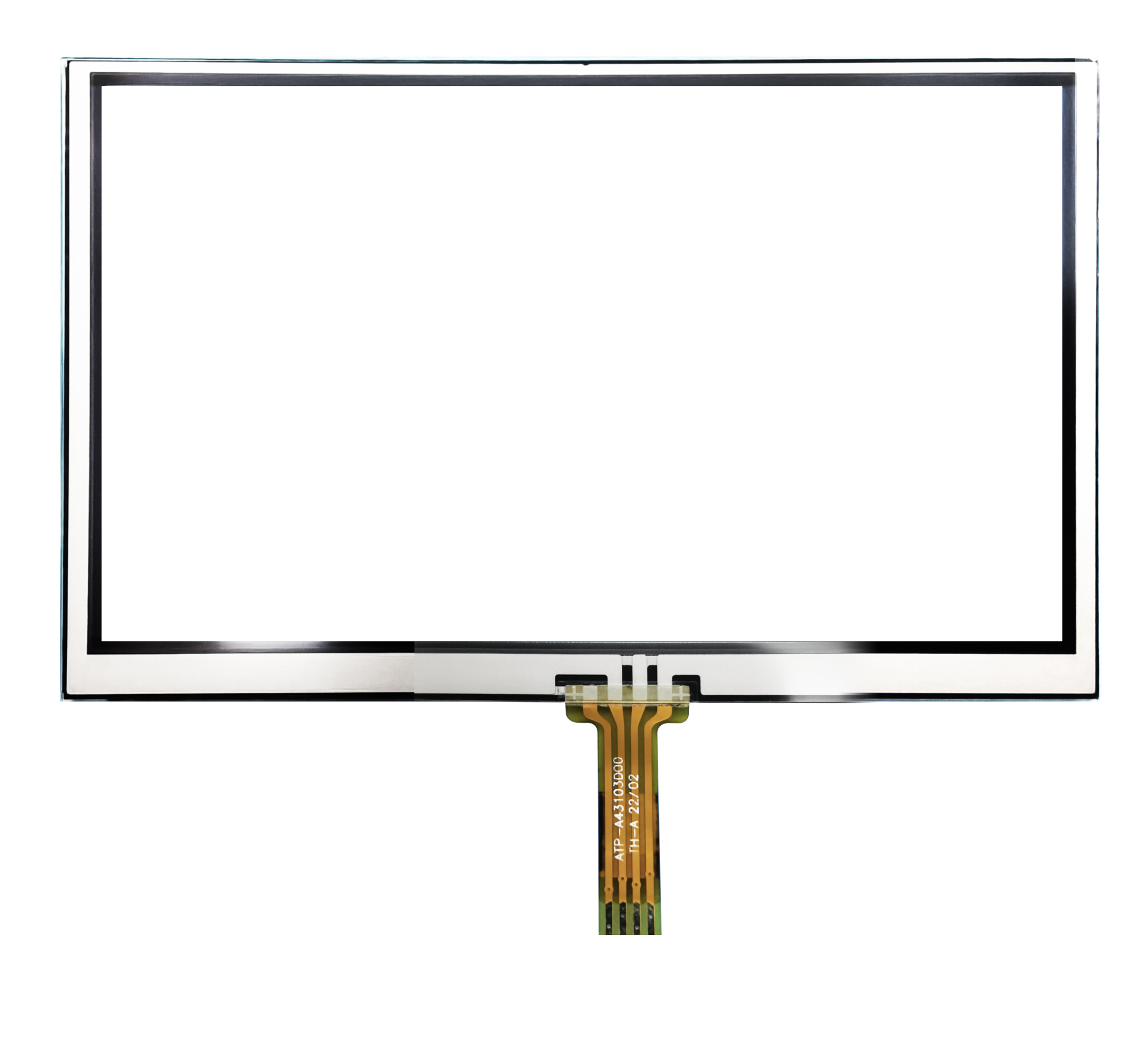
Using screen-printing techniques, four silver electrodes are applied: two on the left and right lateral sides of the lower substrate’s ITO layer, and two on the upper and lower vertical sides of the upper diaphragm’s ITO layer. The sheet resistance of these silver electrodes must be more than 3,000 times lower than that of the ITO layer to ensure proper conductivity. A gap of approximately 0.1 to 0.3 mm is maintained between the upper and lower layers, within which spherical spacer beads are placed. These beads have a height of 5 to 10 μm and are distributed with a diameter of less than 50 μm. The four electrodes are routed out via flexible flat cables, and the upper and lower parts are firmly pressed together using sealant or double-sided adhesive tape to form a complete touch screen assembly. Once this touch screen is attached to an LCD panel and connected to the appropriate control circuitry and interface drivers, it can be integrated into a wide range of end products.
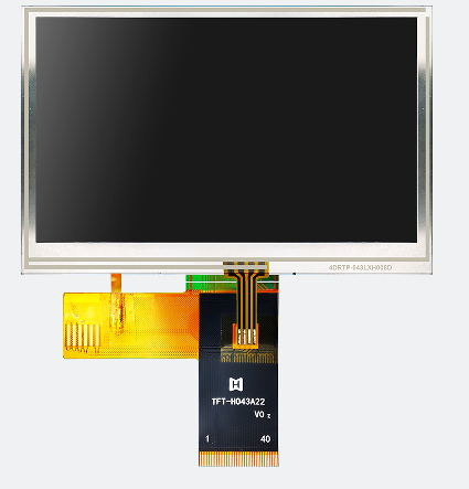
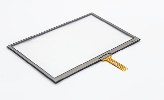
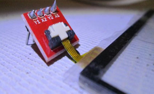
The accompanying images (Figures 1 and 2) show a four-wire resistive touch screen from HOTHMI, illustrating both the standalone unit and its assembled appearance on a display screen.