-300x300.jpg)
Description
Product Overview
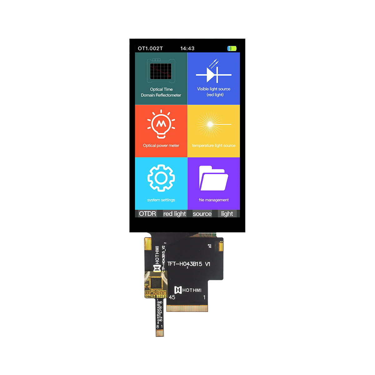
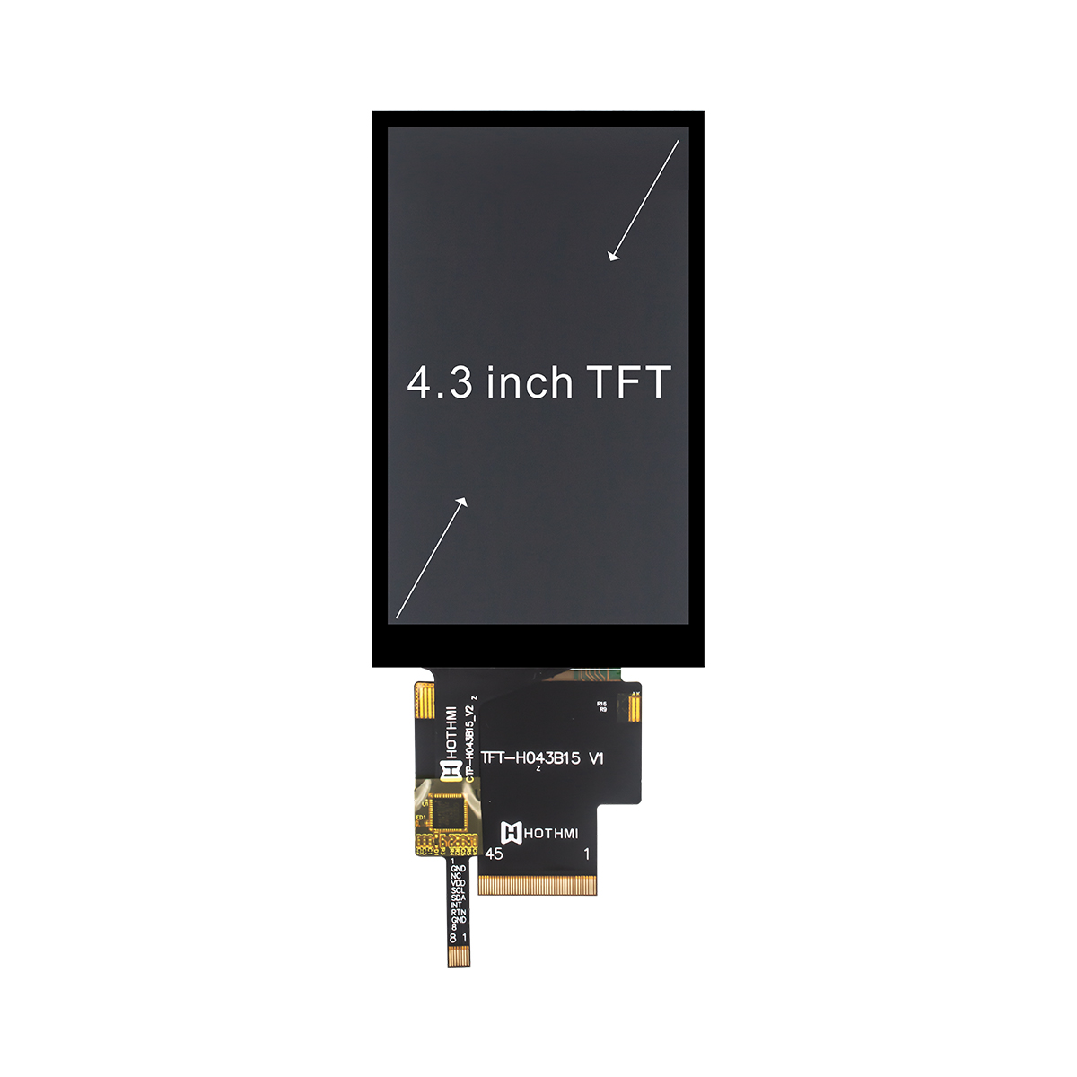
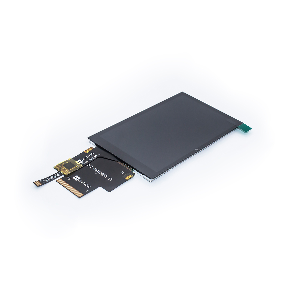
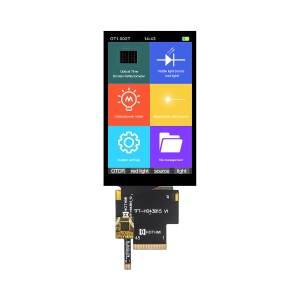
This RGB LCD Display module is a transmissive, normally black TFT LCD that delivers up to 16.7 million rich colors. The core driver chip uses the market-proven ST7701S, ensuring high fluidity in image refresh and excellent color control.
Core Dimensions and Resolution
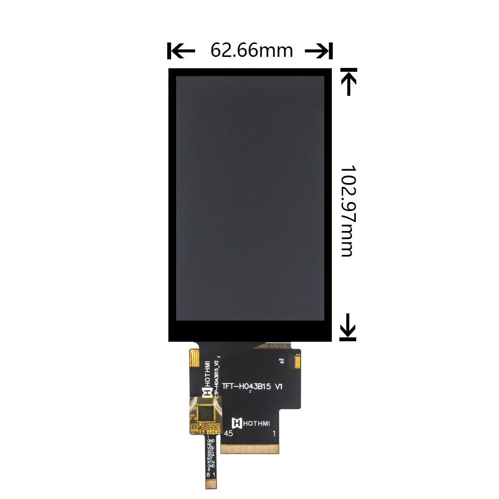
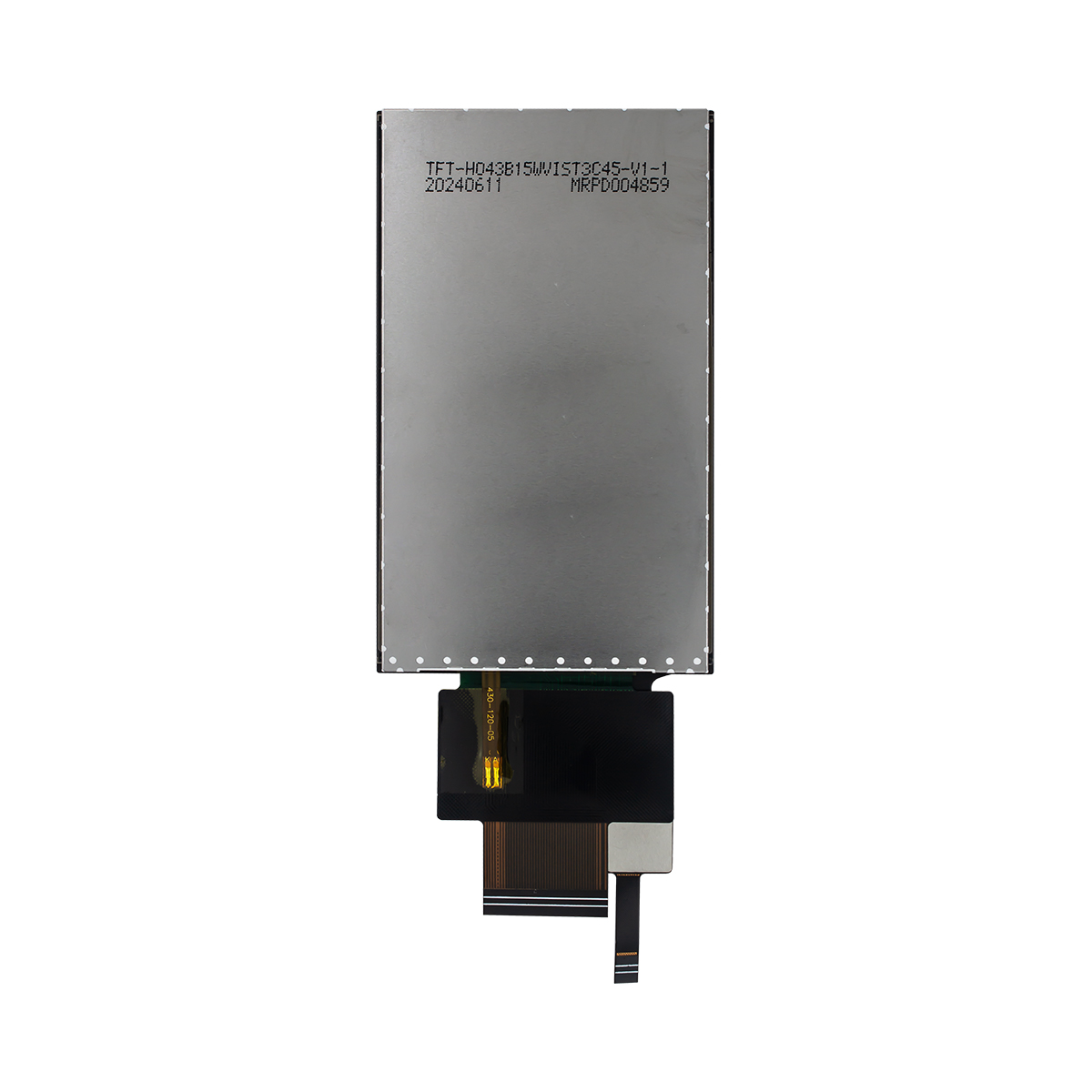
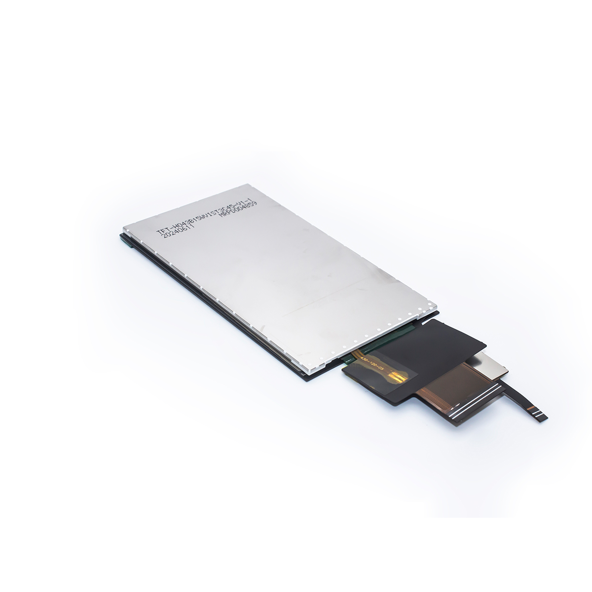
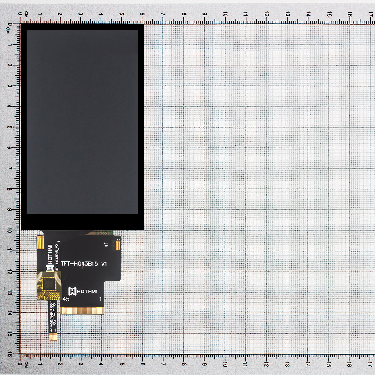
The 4.3-inch RGB LCD Display features a resolution of 480×800 pixels, supports full viewing angles, and is equipped with the ST7701S driver chip. The screen supports RGB and SPI interfaces. The backlight uses 10 white LEDs (5 series, 2 parallel). Operating voltages are 2.8V and 1.8V. It is available in three versions: non-touch, resistive touch (RTP), and capacitive touch (CTP). The capacitive touch version uses the GT911 chip and operates at 3.3V. The operating temperature range is -20°C to +70°C.
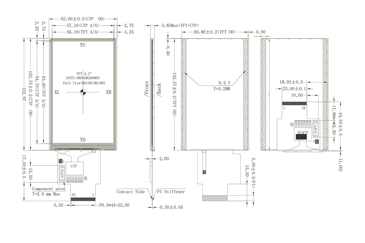
- None touch version:TFT-H043B15WVIST4N45
- Resistive touch (RTP) version: TFT-H043B15WVIST3R45
- Capacitive touch (CTP) version: TFT-H043B15WVIST3C45
Electrical and Environmental Tolerance
This RGB LCD Display module is optimized for demanding industrial and outdoor environments with wide temperature tolerance.
- LCD operating temperature: -20°C to +70°C
- LCD storage temperature: -30°C to +80°C
- Operating voltage: VCI = 2.8V (digital power), IOVCC = 1.8V (I/O system power, typical)
Interface and Wiring Instructions
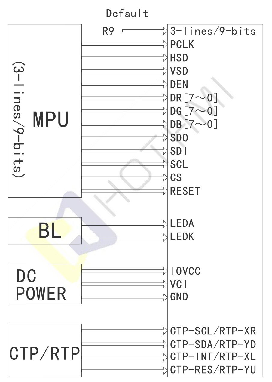
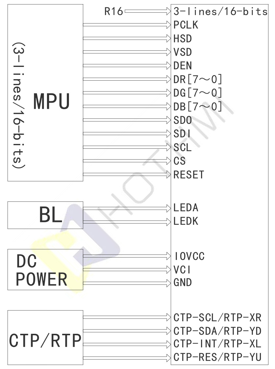
The wiring of this RGB LCD Display module depends on the SPI hardware configuration (R9 or R16) selected on the FPC. There are two wiring schemes.
Pin Description
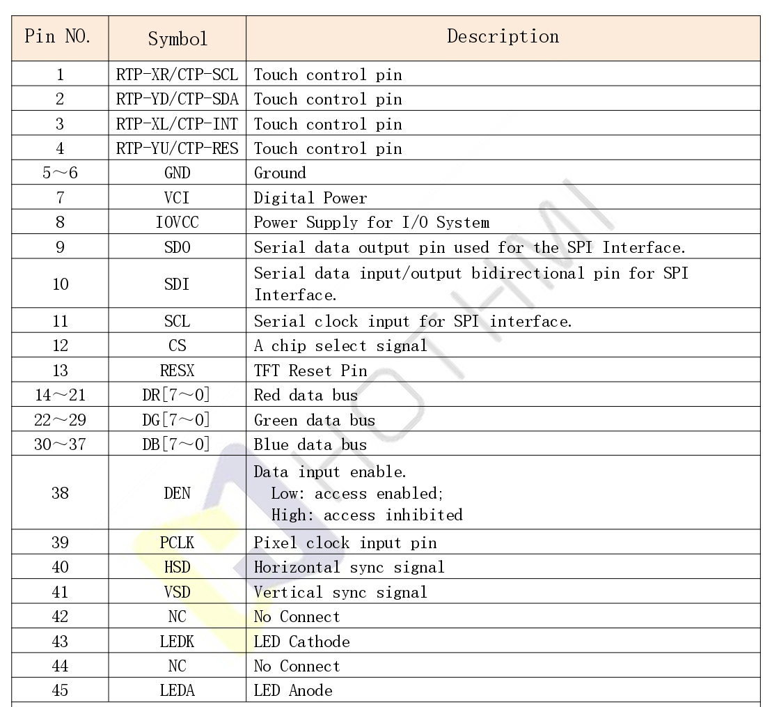
This 4.3-inch RGB LCD Display module uses a 45-pin FPC interface. The pin definition is scientifically arranged, covering display, configuration, power, and touch control.
Backlight and Optical Specifications
High brightness and high color accuracy are key technical features of this RGB LCD Display.
Backlight Configuration
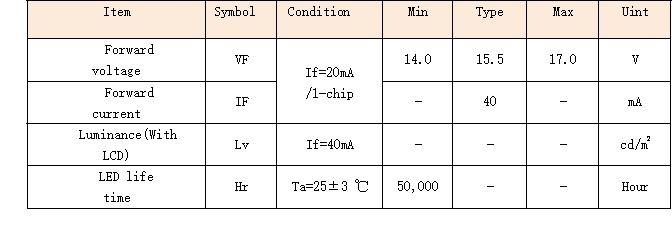
The RGB LCD Display module backlight uses high-brightness white LED particles. A total of 10 LEDs are integrated internally in a 5-series, 2-parallel (5S2P) efficient balanced circuit topology.
- Driving current (IF): Standard test current is 40mA
- Forward voltage (VF): Typical range from 14.0V to 17.0V
- LED lifetime: Over 50,000 hours at 25±3°C (until brightness decays to 50% of initial value)
Optical Performance Highlights
- Full viewing angle (IPS level): Up to 80° in all directions (top/bottom/left/right), no color distortion or inversion
- Ultra-high contrast ratio: 1500:1 static contrast, deep blacks and bright whites, excellent image layering
- Color gamut: 70% based on CIE1931 standard, delivering vivid and accurate colors
Product Highlights of the 4.3 inch RGB LCD Display
- High-dynamic, high-contrast normally black panel: Transmissive normally black LCD technology combined with 1500:1 contrast ratio ensures fine image detail and color layering
- Three-in-one multi-scenario touch options: Natively supports non-touch, resistive touch (RTP), and high-sensitivity capacitive touch (CTP) versions. The capacitive screen uses the mainstream GT911 touch chip with 3.3V I2C interface voltage, making development and debugging very convenient
- Ultra-wide operating temperature, built for industrial use: -20°C to +70°C tolerance, easily handles outdoor climates and high heat inside industrial equipment enclosures
- Highly flexible interface configuration: Fully compatible with 16-bit, 18-bit, and true 24-bit RGB hardware buses, plus 3-wire SPI configuration, enabling seamless connection to various microprocessors (STM32, Linux ARM, FPGA, etc.)
Typical Applications
With its high resolution (480×800) and portrait narrow-bezel physical characteristics, this 4.3-inch RGB LCD Display module is widely used in the following fields:
- Smart home control panels: 86-series wall switches, central air conditioning controllers, smart video intercom terminals
- Medical monitoring and analysis equipment: High contrast and color accuracy clearly display ECG, blood oxygen, and various medical sensor data curves
- Industrial HMI automation: Handheld industrial test instruments, CNC machine touch terminals, PLC expansion displays; high temperature resistance ensures stable 24/7 operation
- Smart mobility and automotive displays: High-end electric two-wheeler dashboards, charging pile control screens, portable car navigation auxiliary screens
Core Initialization Code Example (TFT Display Initialization Code)
To help developers quickly debug and light up this RGB LCD Display, the following shows the low-level core initialization and power-on reset example code from the datasheet, based on the main controller configuration.
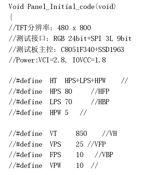
For the complete register initialization source code, please contact our technical support team for one-on-one hardware guidance.
Technical Q&A about 4.3 inch RGB LCD Display
Q1: The datasheet mentions two SPI configurations: 9-bit and 16-bit. What determines this? How do I switch?
A1: This is determined by the physical placement of resistors R9 and R16 on the FPC. When the resistor is soldered at position R9, the system selects 9b_SPI (fall) mode (data latched on falling edge). When the resistor is moved to position R16, it selects 16b_SPI (rise) mode (data latched on rising edge). The default factory configuration is typically R9, 3-line 9-bit SPI mode.
Q2: Can I use RGB 16-bit (RGB565) format to reduce controller I/O pins? What about unused pins?
A2: Yes, you can. The driver chip supports changing to 16-bit color format via SPI commands (or pin configuration) (VIPF(3:0)=0101). In this mode, the main controller only needs to connect DB(0:4), DG(0:5), and DR(0:4) — a total of 16 data lines. According to the datasheet, all unused parallel data bus pins on the RGB interface must be tied to GND and must never be left floating to avoid high-frequency noise interference.
Q3: What is the communication voltage for the capacitive touch screen (CTP) interface? Can it share the TFT LCD I/O voltage?
A3: There is an important development detail here: Although the TFT LCD I/O power (IOVCC) is typically 1.8V, the CTP’s integrated GT911 chip requires VDD/IOVDD of 3.3V for its I2C communication and driving voltage. The datasheet specifically notes: “The CTP IIC communication voltage is 3.3V.” Therefore, when designing your main board PCB, ensure that you provide 3.3V level shifting logic for the CTP’s I2C lines (SCL/SDA/INT/RES). Do not drive them directly with 1.8V, as this may cause the touch function to fail or not work.