Understanding the IIC Interface: A Complete Guide to LCD and CTP Display Connectivity
Introduction to Display Interfaces in Embedded Systems
In modern embedded system engineering, establishing reliable data communication between a host processor—whether a microcontroller (MCU), microprocessor (MPU), or central processing unit (CPU)—and a liquid crystal display module is a fundamental task. Multiple hardware interface standards exist for this purpose. Among them, the IIC interface (Inter-Integrated Circuit, also referred to as I²C) stands out as one of the most prevalent and efficient serial communication solutions, particularly valued for its minimal pin count and straightforward implementation.
Fundamental Principle 1: Why LCDs Require AC Drive Waveforms
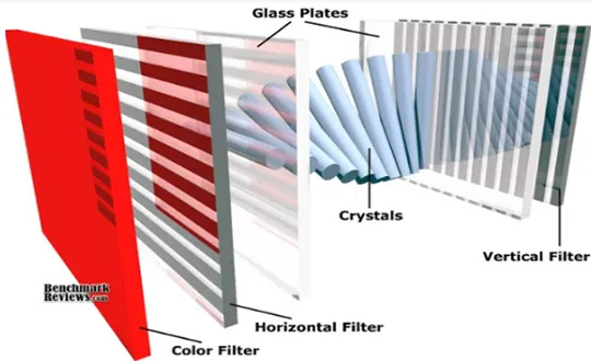
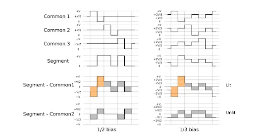
A critical yet often overlooked aspect of LCD operation is its drive signal characteristic. Liquid crystal displays cannot be driven with direct current. When a DC voltage is continuously applied to the LCD panel, it triggers irreversible electrochemical degradation of the liquid crystal material, ultimately destroying the display.
To prevent this, all LCDs must be driven with alternating current signals, and critically, the net current integral over each complete drive cycle must equal zero—meaning the DC component must be completely eliminated. This AC-driven approach guarantees long-term display stability and extends the operational lifespan of the panel.
Fundamental Principle 2: The Distinct Roles of LCD Controllers and Drivers
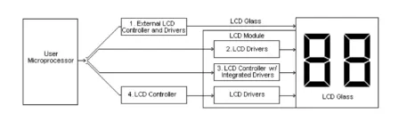
The LCD driving system is typically architected around two categories of integrated circuits, each serving a distinct purpose:
- Common Driver (Row Driver): This IC outputs scanning signals that sequentially activate entire rows (or commons) of the display matrix, determining which horizontal line is active at any given moment.
- Segment Driver (Column Driver): This IC generates the necessary column-wise signal patterns that define visible elements—whether characters, graphics, or individual pixels—on the activated rows.
The Bridge Role of the Controller IC
The controller IC acts as the intelligent intermediary between the MPU and the aforementioned drivers. Its primary functions include:
- Receiving encoded display data (typically in ASCII or JIS formats) from the MPU.
- Temporarily buffering this data in its internal RAM.
- Converting the buffered data into serialized pixel-mapping patterns.
- Transmitting these patterns to the driver ICs for final rendering on the screen.
Integrated Driver/Controller Chips
In many graphic display modules, a combined driver/controller chip is increasingly common. This single-chip solution not only stores incoming display data from the MPU but also directly interprets MPU-issued commands. It simultaneously manages the timing and voltage levels for both common and segment drivers, significantly reducing external component count and simplifying PCB layout.
The IIC Bus Interface Explained
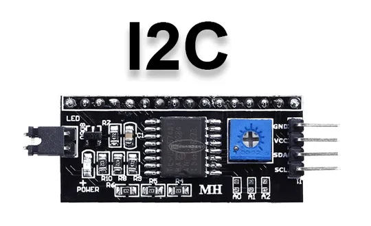
Among all available interface options, the IIC interface holds a unique position due to its exceptional simplicity and versatility. It operates as a two-wire, serial, synchronous communication bus.
The Two Essential Signal Lines
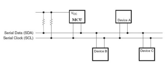
The physical layer of the IIC bus consists of only two bidirectional lines:
- SCL (Serial Clock Line): This line carries the clock signal generated by the bus master device (typically the MPU or MCU). It synchronizes all data transfers across the bus, ensuring that every bit is sampled at the correct moment.
- SDA (Serial Data and Address Line): This line is responsible for the bidirectional transmission of both data frames and slave device address information. Every slave device on the bus has a unique 7-bit or 10-bit address, allowing the master to selectively communicate with specific components.
Why Choose the IIC Interface for Displays and Touch Panels?
The widespread adoption of the IIC interface in display applications is driven by several key technical and practical advantages:
- Minimal Pin Usage: With only two signal lines required, the IIC bus conserves valuable I/O pins on the host processor, leaving more resources for other peripherals.
- Simplified Routing: The two-wire topology drastically reduces PCB trace complexity, leading to smaller board sizes and lower manufacturing costs.
- Moderate Data Rate: While not suited for high-resolution video streaming, the IIC bus offers sufficient bandwidth (standard up to 100 kbit/s, fast up to 400 kbit/s, and high-speed up to 3.4 Mbit/s) for character-based LCDs, dot-matrix graphic displays, small TFT color panels, and capacitive touch panel controllers, which typically transmit coordinate and gesture data rather than heavy pixel information.
- Multi-Slave Support: A single IIC bus can accommodate multiple slave devices (e.g., an LCD controller and a CTP controller simultaneously) using address-based addressing, enabling cohesive system integration without additional wiring.
Practical Applications of the IIC Interface
The IIC interface is the de facto standard for connecting host processors to:
- Monochrome digital character LCD modules (e.g., 16×2 alphanumeric displays).
- Small to medium dot-matrix graphic LCDs.
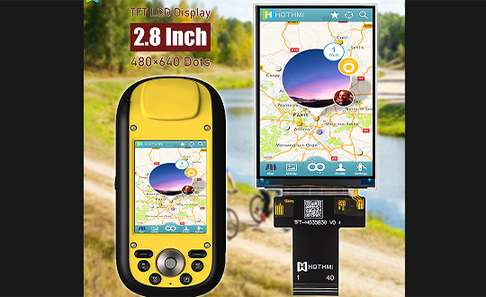
- Low-resolution TFT color displays commonly found in handheld devices and IoT terminals.
- The vast majority of capacitive touchscreen panels used in industrial, consumer, and automotive applications.
Conclusion
Understanding the IIC interface is essential for embedded designers working with LCD and CTP modules. Its elegant two-wire architecture, combined with robust multi-device addressing and sufficient performance for control-oriented display tasks, makes it a reliable and cost-effective choice. By adhering to proper AC drive principles and leveraging the functional division between controllers and drivers, engineers can build stable, long-lasting display systems that integrate seamlessly with modern processors.
For more product options, please browse our product catalog.