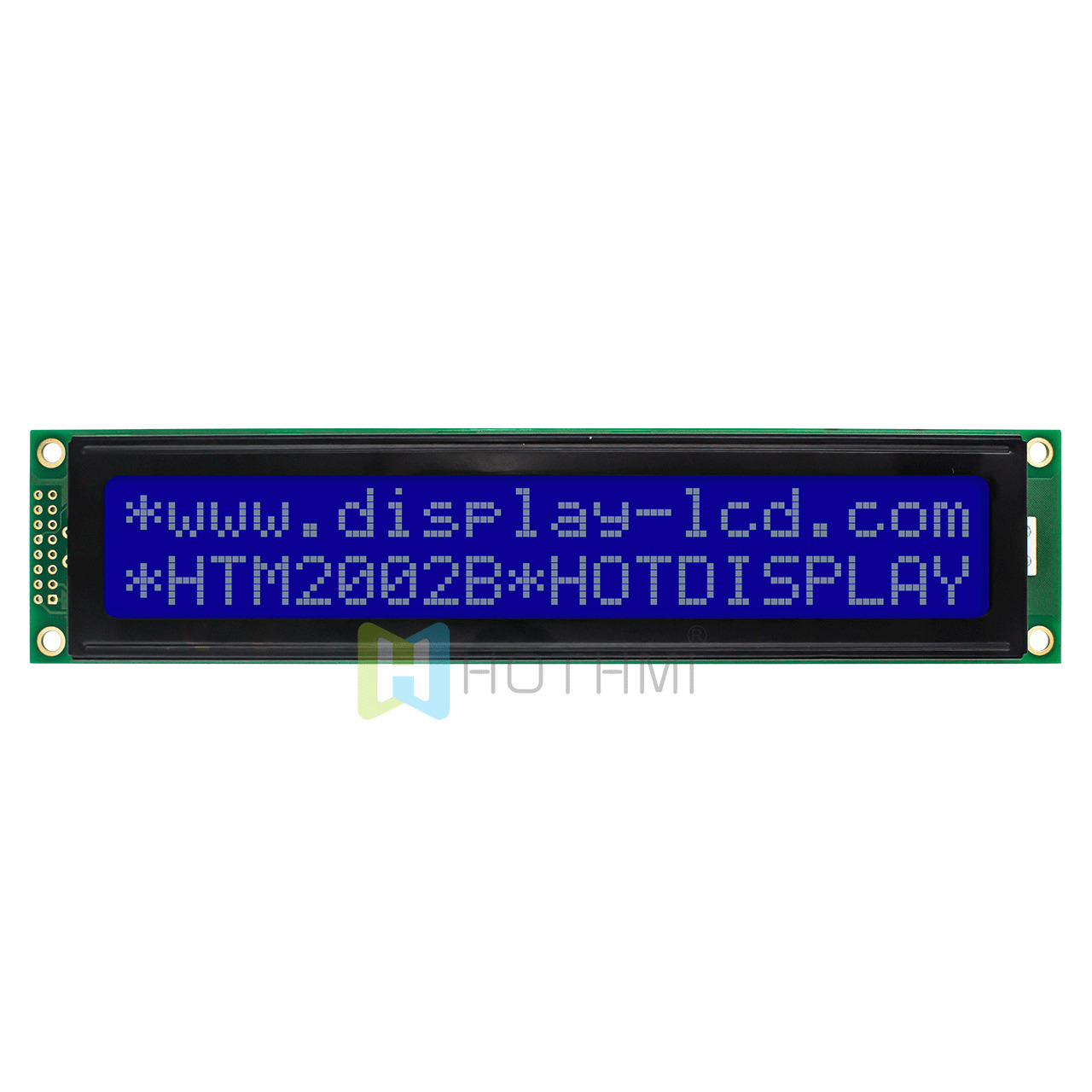
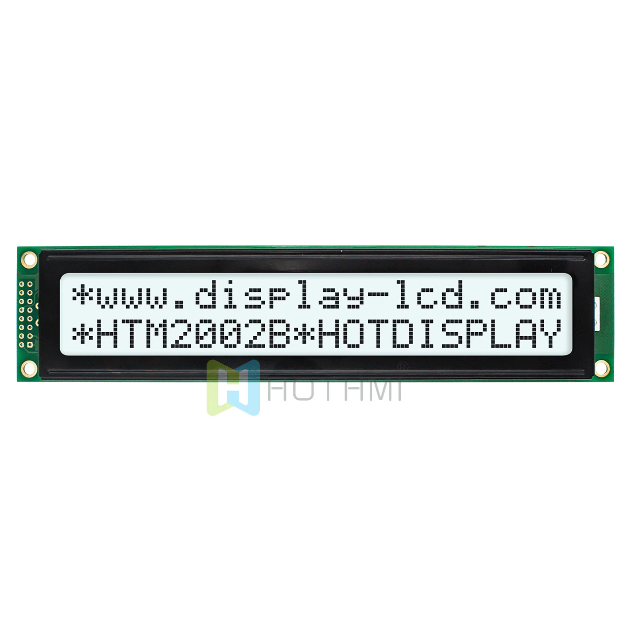
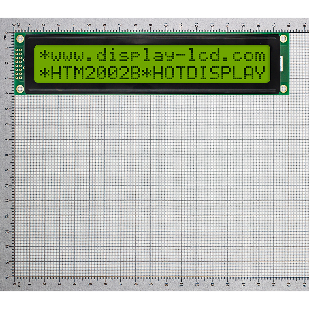
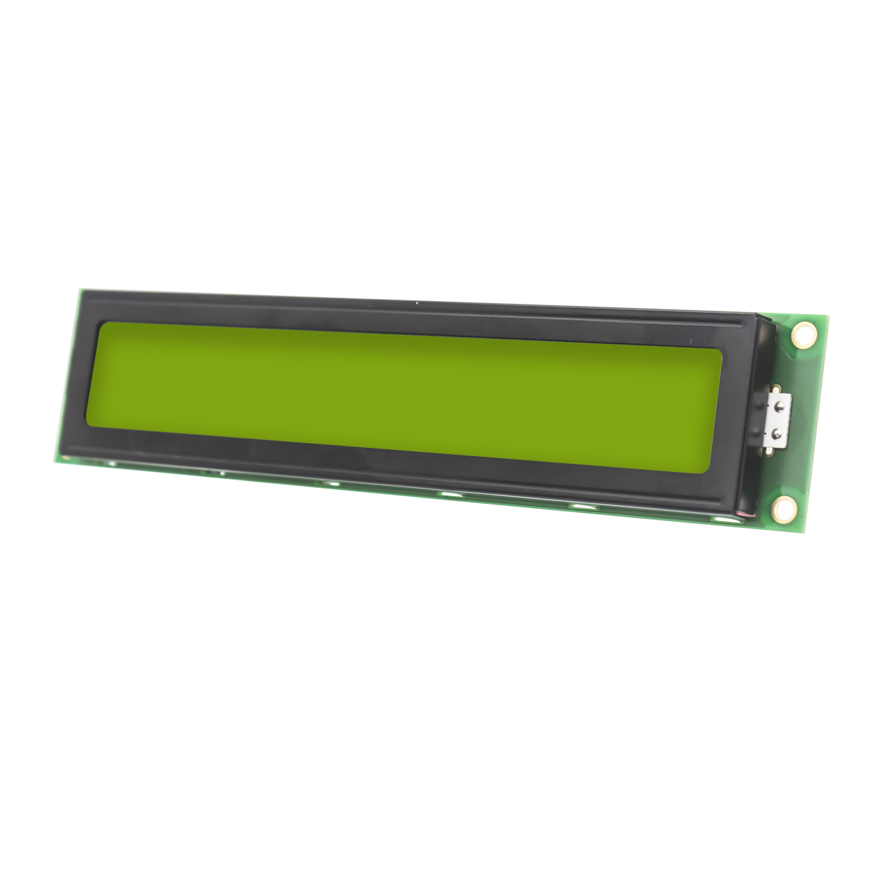
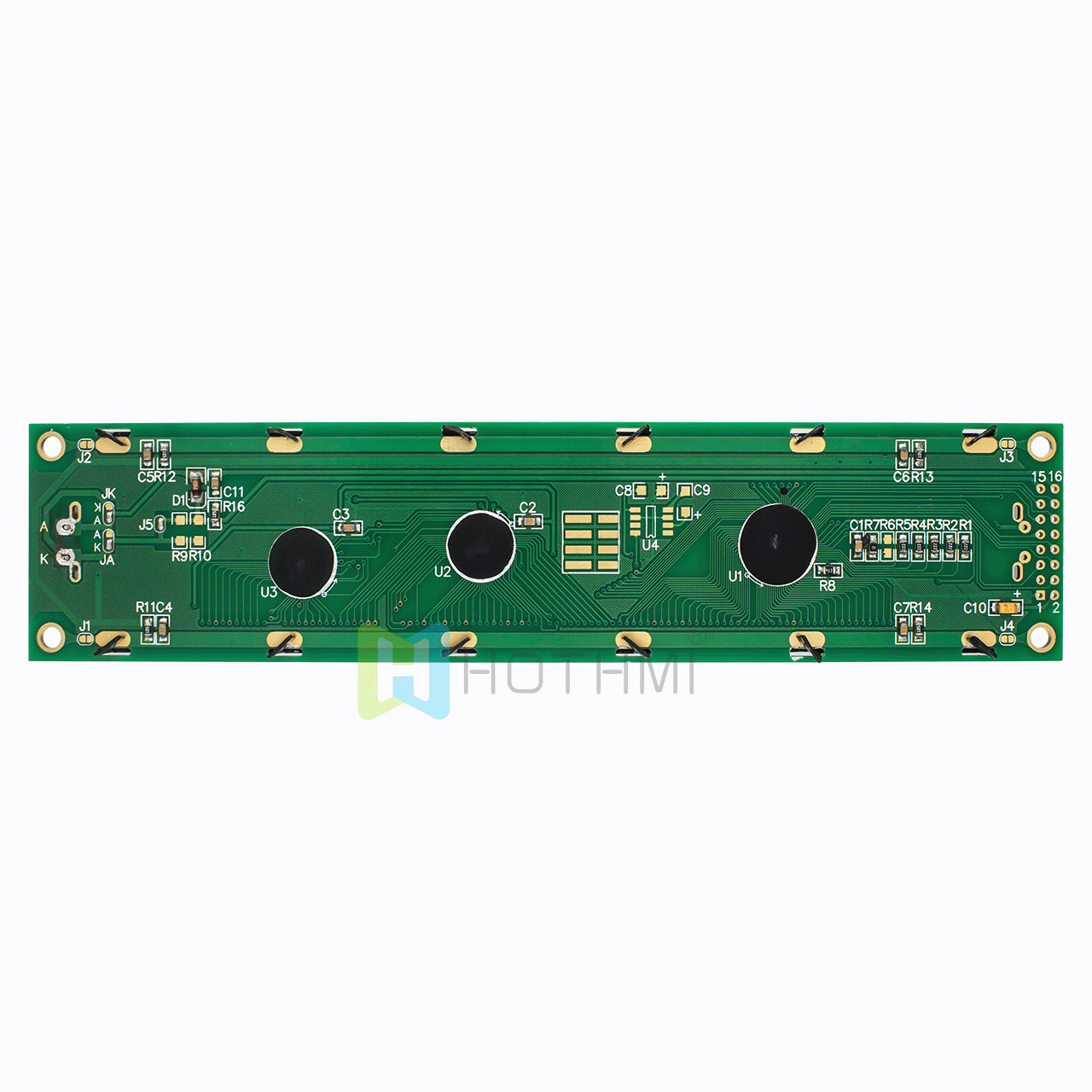
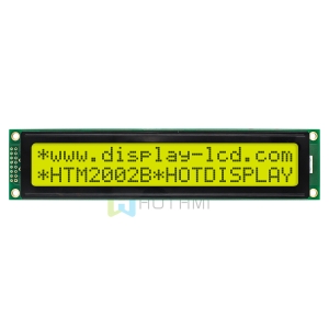
20×2 LCD Display Monochrome Module ST7066U
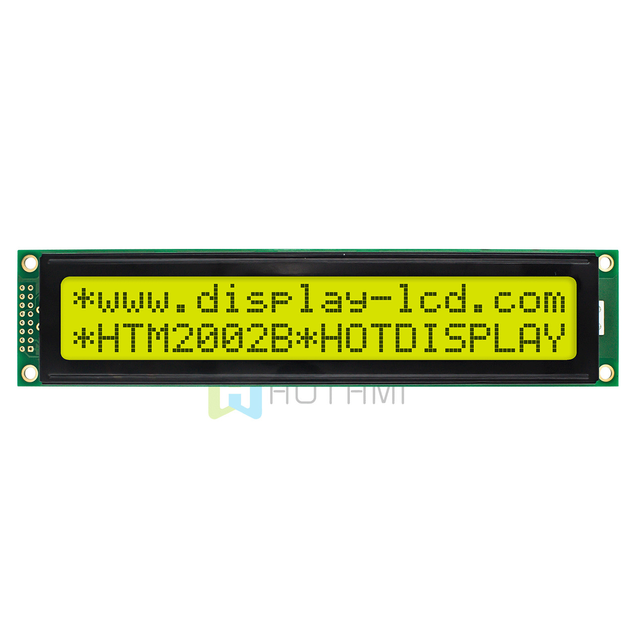
- Model: HTM2002B
- Type: 20×2 Character LCD Module
- Overall dimensions (mm): 180.0×40.0x11.0
- VA size (mm): 149.0×23.0
- Working temperature: -10℃~+60℃
- Supply voltage: 5.0V
- Driver chip:ST7066U
$38.00
In stock
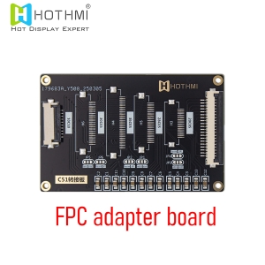
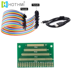
This item: 20x2 LCD Display Monochrome Module ST7066U
$38.00
$38.00
Description
Product Overview and Core Features of 20×2 LCD Display
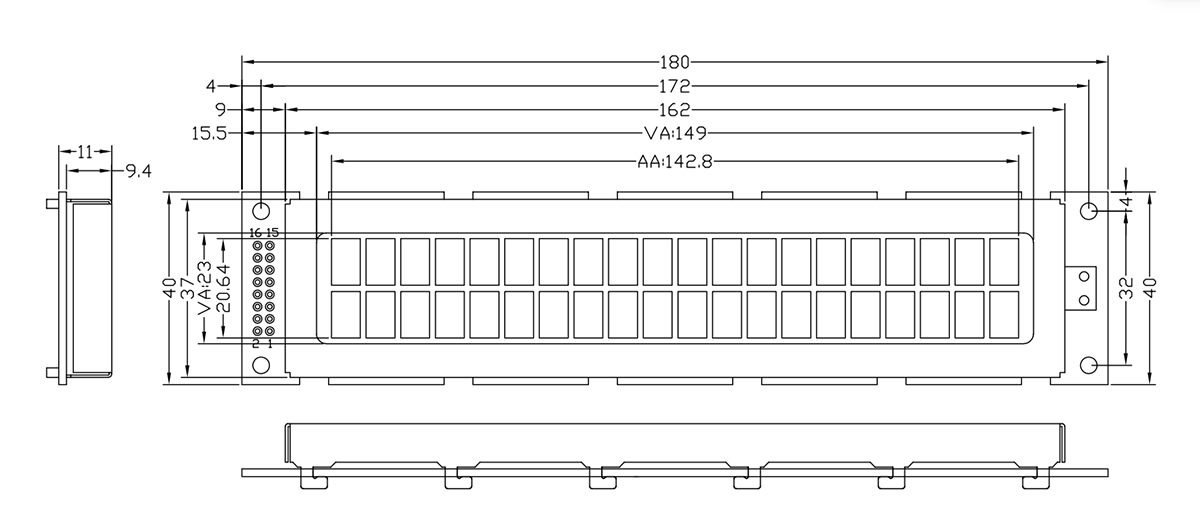
The HOTHMI HTM2002B is a 20×2 LCD display (20 characters per line × 2 lines) offering excellent readability in any lighting conditions: clearly visible indoors with backlighting, and also clearly readable under direct sunlight with reflected light (no white screen). It integrates an ST7066U (or equivalent) controller with a 1/16 duty cycle, 1/5 bias voltage, 5.0V operating voltage, a 6 o’clock viewing angle, and dimensions of 180×40×11mm (maximum thickness 15.5mm). The viewable area is 149×23mm, and it features a standard 16-pin interface (VSS, VDD, VO, RS, R/W, E, DB0-DB7, A/K). The operating temperature range is -10°C to +60°C (storage temperature range -20°C to +70°C). It is ideal for industrial control, instrumentation, and embedded devices.
- Mainstream Controller IC, Mature Ecosystem: The 20×2 LCD Display module integrates ST7066U or industry-standard equivalent compatible controller IC. This means its underlying instruction set is fully compatible with all mainstream open-source libraries.
- Optimal Viewing Angle & Superior Contrast: The product features a 6 o’clock optimal viewing direction design, perfectly matching the upward or direct viewing angles of most instrument panels or equipment surfaces. With precise 1/16 duty cycle and 1/5 bias ratio, it ensures sharp character edges without blurring or ghosting, maintaining high contrast even with continuous long-term display.
- Ultra-Slim & Robust Physical Structure: The module’s overall dimensions are 180mm × 40mm, with thickness controlled between 11.0mm and 15.5mm (including the maximum thickness of the bottom LED backlight). The visual area reaches 149mm × 23mm. Character LCD Displays are generously sized with precisely calibrated dot pitch spacing and shock-resistant construction, facilitating easy assembly in compact equipment enclosures.
- Industrial-Grade Wide Temperature Durability: Specially optimized for harsh industrial environments, the standard operating temperature spans -10°C to +60°C, with storage temperature supporting -20°C to +70°C. Whether used in substations, outdoor cabinets, vehicle-mounted equipment, or hot factory workshops, it ensures stable 24/7 operation without failure.
Pin Description and Interface Definition of 20×2 LCD Display
To facilitate rapid circuit schematic and PCB design, this 20×2 LCD Display module uses the industry-standard 16-pin single-row pin header interface with 2.54mm pin spacing. The detailed function and electrical definitions of the 16 pins are as follows:

Wiring Guide and Operating Modes of 20×2 LCD Display
In actual hardware development, this 20×2 LCD Display supports both 8-bit and 4-bit parallel modes.
8-bit Parallel Wiring (Full-Speed Mode)
- Power and Backlight: Pin1 (VSS) → GND; Pin2 (VDD) → 5V; Pin15 (A) → 5V via 10–100Ω resistor; Pin16 (K) → GND.
- Contrast: 10K pot between 5V and GND, wiper to Pin3 (VO).
- Control: Pin4 (RS) & Pin6 (E) to GPIO; Pin5 (R/W) → GND (write-only).
- Data: Pin7–14 (DB0–DB7) to an 8-bit port.
- Use: High-speed, pin-rich systems.
4-bit Parallel Wiring
- Wiring: Power, contrast, control same as 8-bit. Data: DB0–DB3 (Pin7–10) unconnected; only DB4–DB7 (Pin11–14) to 4 GPIO pins.
- How it works: Each byte sent as high 4 bits then low 4 bits over same 4 lines, each followed by an E pulse to latch.
- Trade-off: Saves 4 I/O pins; speed halved but fine for text display.
Backlight Design and Optical Specifications
- Long Life and Vibration Resistance: Compared to older CCFL backlights, LED solid-state backlight contains no high-voltage components and offers excellent vibration and shock resistance. Backlight life typically exceeds 50,000 hours.
- Intelligent Power Control: Under standard 5.0V drive, backlight current consumption is very low. Engineers can connect Pin 15 (A) to a PWM-capable microcontroller pin, and by dynamically adjusting the PWM duty cycle via software, easily achieve multi-level backlight brightness adjustment – automatically dimming at night and brightening during the day – significantly reducing overall power consumption of the embedded terminal.
Typical Applications of 20×2 LCD Display
Thanks to its high system stability, extremely low failure rate, and highly standardized instruction architecture, this 20×2 LCD Display module has become deeply embedded in numerous professional and consumer hardware fields:
- Industrial Control and Automation Panels: PLC peripheral display units, CNC machine status windows, VFD parameter configuration panels, equipment room environmental monitoring displays.
- Smart Electronic Instruments: High-precision digital multimeter displays, three-phase digital power meters, lab DC power supplies, industrial gas detectors, electronic weighing instruments.
- Commercial and Smart Logistics Terminals: Vehicle taximeter displays, vending machine user prompt screens, barcode scanner base stations, cafeteria payment terminals.
- Medical and Environmental Monitoring Equipment: Portable medical monitor parameter screens, small sterilizer control systems, water quality analyzers.
- DIY Electronics and Educational Projects: Classic teaching equipment for Arduino, Raspberry Pi, STM32, ESP32, and other mainstream microcontroller development boards; widely used in university EE graduation projects and research.
Technical FAQ of 20×2 LCD Display
Q1: I’m using a 3.3V microcontroller. How do I safely and efficiently connect this 5V 20×2 LCD Display?
A: You can connect them directly by following these two key points:
- Direct Logic Connection:At 5V VDD, the LCD’s high-level input threshold is 2.2V–2.5V. Since 3.3V MCU outputs exceed 3.0V, the LCD recognizes them perfectly. Set MCU GPIOs to push-pull output for a direct connection without level shifters.
- Safe Write-Only Setup:Solder Pin 5 (R/W) directly to GND. This locks the LCD in “write-only” mode, preventing any 5V back-feeding to protect your 3.3V MCU. Connect the module VDD and the contrast potentiometer to 5V.
Q2: What are the timing and delay requirements for the Enable (E) pin pulse in 4-bit mode?
A: The E pin acts as a data latch clock. Follow these strict timing rules:
- Pulse Sequence:Set RS and R/W levels -> output 4-bit data -> pull E high (hold for 1–2µs to meet the 150ns setup time) -> pull E low (falling edge latches data).
- Execution Delays:Standard commands (writing characters, setting cursor) take 40µs–100µs. Special commands like “Clear Screen” or “Return Home” require a much longer delay of 1.5ms–3ms before sending the next instruction.
Additional information
| Weight | 0.2 kg |
|---|
Attributes
| item | Specification content | unit |
| model | HTM2002B | |
| words × lines | 20words × 2lines | dots |
| Module size | 180.0 × 40.0 × 11.0 (MAX) | mm |
| VA size | 149.0(W) × 23.0(H) | mm |
| AA size | 142.8 × 20.64 | mm |
| Point (pixel) size | 0.56 × 0.66mm | mm |
| Point (pixel) spacing | 1.22(W) × 1.22(H)mm | mm |
| IC | ST7066U | |
| Applied voltage | 5V | V |
| Drive mode | 1/16 duty cycle | |
| type | Character LCD Module |
Related products