Description
Arduino Color Display Product Overview
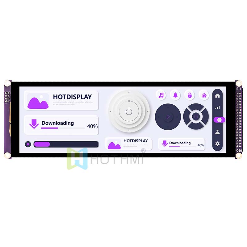
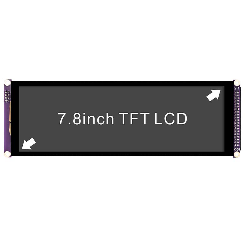
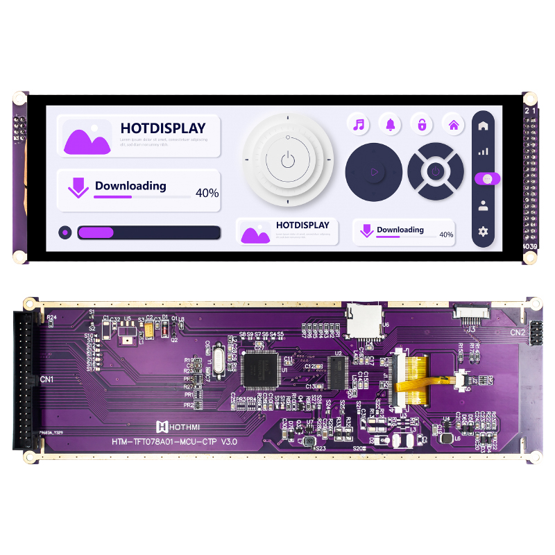
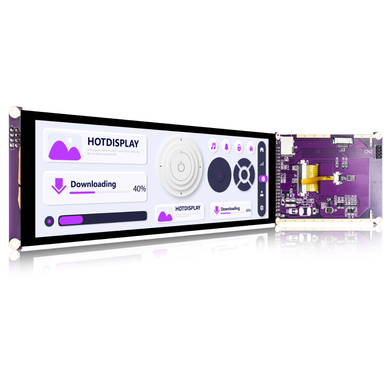
The HTM-TFT078A01-MCU-CTP is an industrial-grade, ultra-wide 7.84-inch TFT LCD Arduino Color Display module developed by HOTHMI. Designed for non-standard chassis spaces, custom human-machine interface (HMI) projects, and embedded system development, this module effectively solves the engineering challenge of installing conventional 4:3 or 16:9 screens in narrow enclosures. With full-viewing-angle IPS technology and a resolution of 400 x 1280 Dots, it delivers crisp, detailed visuals within a compact long-strip form factor.
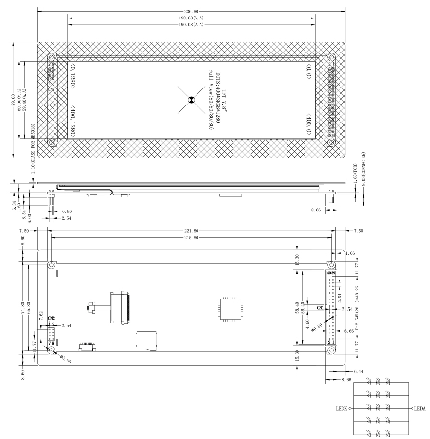
For open-source hardware and embedded engineering, this module serves as an ideal solution for building an advanced Arduino Color Display. It integrates a highly reliable RA8889 driver chip and a GT911 capacitive touch panel, supporting SPI-4L communication for smooth, responsive touch interaction. Key physical specifications include outer dimensions of 221.8 × 71.8 × 9 mm, an active display area of 190.88 × 60.2 mm, and a high-brightness white LED backlight delivering 450 cd/m² luminance with a 1500:1 contrast ratio for vivid colors and fine detail. Operating at VCC 3.3V and backlight BL_VCC 5.0V, the module offers excellent environmental tolerance, functioning stably from -20°C to +70°C—making it well suited for automotive dashboards, smart controls, industrial displays, and other applications requiring a long-strip screen.
Key Technical Highlights
Unique Wide-Strip Aspect Ratio with IPS Full-View Optics
This Arduino Color Display module breaks from conventional formats with an active area of 190.88 mm (H) × 60.2 mm (V), creating a distinctive ultra-wide display window. The panel uses advanced IPS technology, achieving full-angle viewing performance with 80°/80°/80°/80° typical viewing angles in both horizontal and vertical directions.
Hardware Rendering Engine: Powerful RA8889 Driver Core
Driving a display with over 512,000 physical pixels would impose a heavy burden on SPI bus bandwidth and MCU RAM if left to the host controller for pixel-by-pixel refresh. This Arduino Color Display resolves that challenge by integrating the high-performance RA8889 LCD driver IC, which offers:
- Built-in frame buffer: The module includes dedicated video memory, so image buffering is handled on the display side, freeing valuable RAM on the host MCU.
- Hardware geometry engine: Supports direct drawing of lines, rectangles, circles, and other shapes via simple commands, eliminating complex per-pixel calculations by the main controller.
- BTE (Block Transfer Engine): Built-in graphics accelerator for hardware-accelerated image copying, dynamic scrolling, picture-in-picture, and alpha blending—enabling smooth GUI performance even on microcontrollers like Arduino.
Rugged Industrial-Grade Durability and Reliability
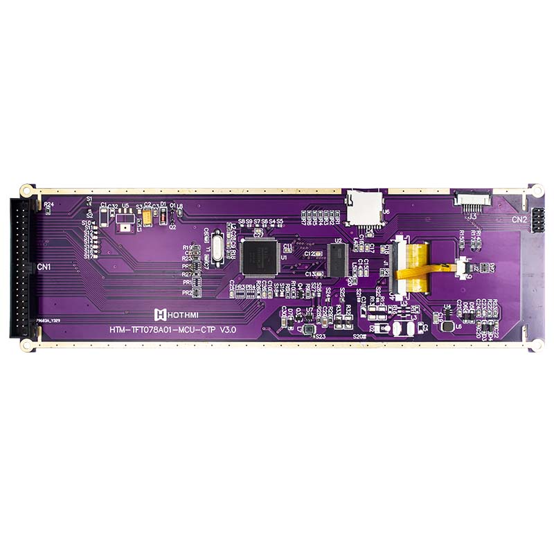
With outer dimensions of 221.8 (H) × 71.8 (V) × 9 (D) mm, the Arduino Color Display module features a sturdy PCB backplate that protects the fragile edges of the LCD glass.
- Precision touch: The GT911 capacitive touch controller offers stable multi-touch support with built-in noise immunity algorithms and a scratch-resistant surface.
- Wide-temperature operation: The Arduino Color Display operates from -20°C to +70°C and can be stored from -30°C to +80°C, ensuring long-term stability whether exposed to internal heat buildup in sealed enclosures or sub-zero outdoor conditions.
Interface Pinout
This Arduino Color Display module connects to the host via two physical interfaces:
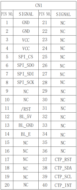
- CN1 – Main interface for system power, SPI-4L display bus, and I2C touch signals.
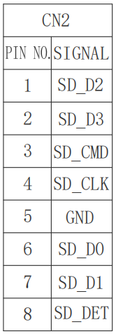
- CN2 – Expansion interface for onboard SD card slot signals, enabling storage of large image files or font libraries.
CN1 Core Main Interface Pin Definition Table
CN2 Expansion SD Card Interface Pin Definition Table
Application Scenarios
- Network server rack status monitoring: Installed on the front panel of 2U/3U rackmount network switches or servers, this display independently shows real-time charts of power efficiency, hardware temperature, and system health without occupying primary display channels.
- High-end smart home control panels: Flush-mounted in walls or on premium appliances, it can simultaneously present multiple security camera feeds, long-term energy consumption trend graphs, and scrolling weather calendars, enhancing the high-tech aesthetic of the HMI.
- Industrial automation for CNC machine tools: Ideal for precision control instruments that require horizontal display of waveforms, axis motion trajectories, or laser cutting paths, with capacitive touch for accurate on-site parameter adjustments.
Technical Q&A for Arduino Color Display
Q1: How do I connect this 7.84-inch long-strip display to an Arduino board, and what electrical details should I consider for wiring?
A: When building an Arduino Color Display with this large 7.84-inch module, the primary considerations are level shifting and power distribution. The module’s system logic voltage (VCC) is standard 3.3V, while traditional Arduino Uno or Mega 2560 boards output 5V logic-high on their I/O pins. Never connect the Arduino’s 5V pins directly to the screen’s /SPI_CS, SPI_SCK, or SPI_SDI—this will instantly damage the RA8889 driver IC’s input buffers. You must insert a high-speed bidirectional level translator (e.g., 74LVC245 or CD4050B) between the host and the display.
For power, the high-brightness backlight array draws up to 400mA at full load. The onboard 3.3V or 5V LDO regulators on Arduino boards cannot handle this current draw, and attempting to do so will cause the board to overheat and repeatedly reset. The proper engineering approach is to use an external 5V/2A regulated power supply: connect its positive output to the module’s BL_5V (Pin 12) and its negative to BL_GND (Pin 13). Additionally, step down that same external supply to 3.3V via a separate regulator and feed it to the module’s VCC (Pins 3, 4). Finally, tie the external power supply’s ground to the Arduino’s GND for common signal reference.
From minor concept tweaks to full custom redesign & development, our engineering team offers end-to-end technical support. Feel free to contact us for custom display demands or technical issues during product selection.