Description
Display COG 2.6 inch 240X160 Product Overview and Core Technical Specifications
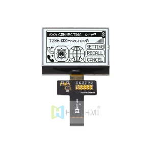
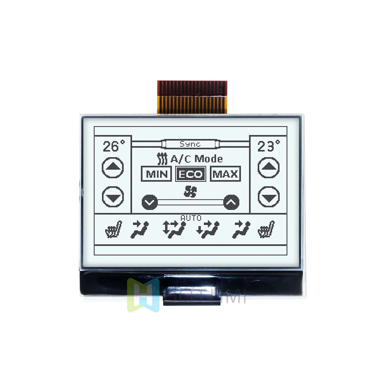
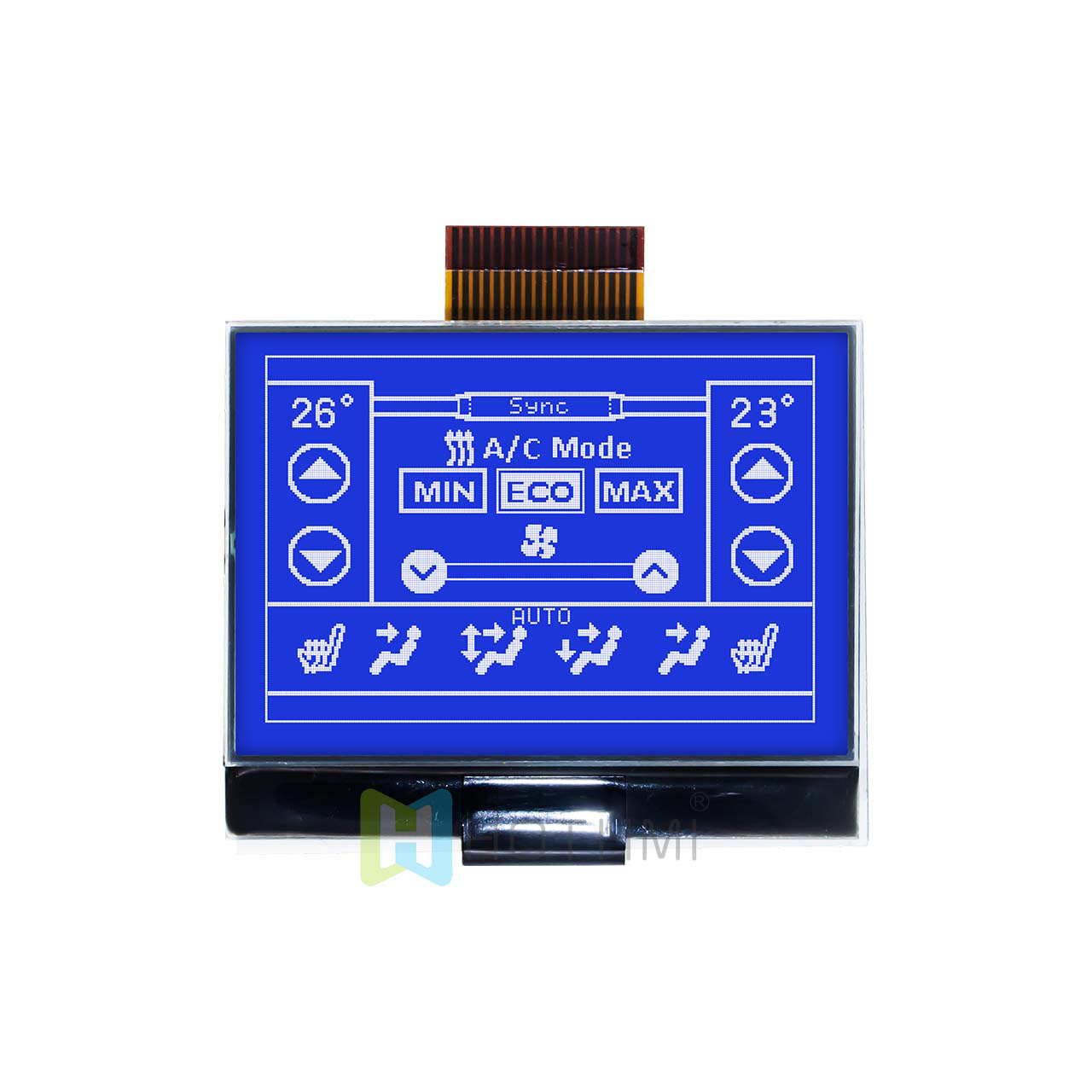
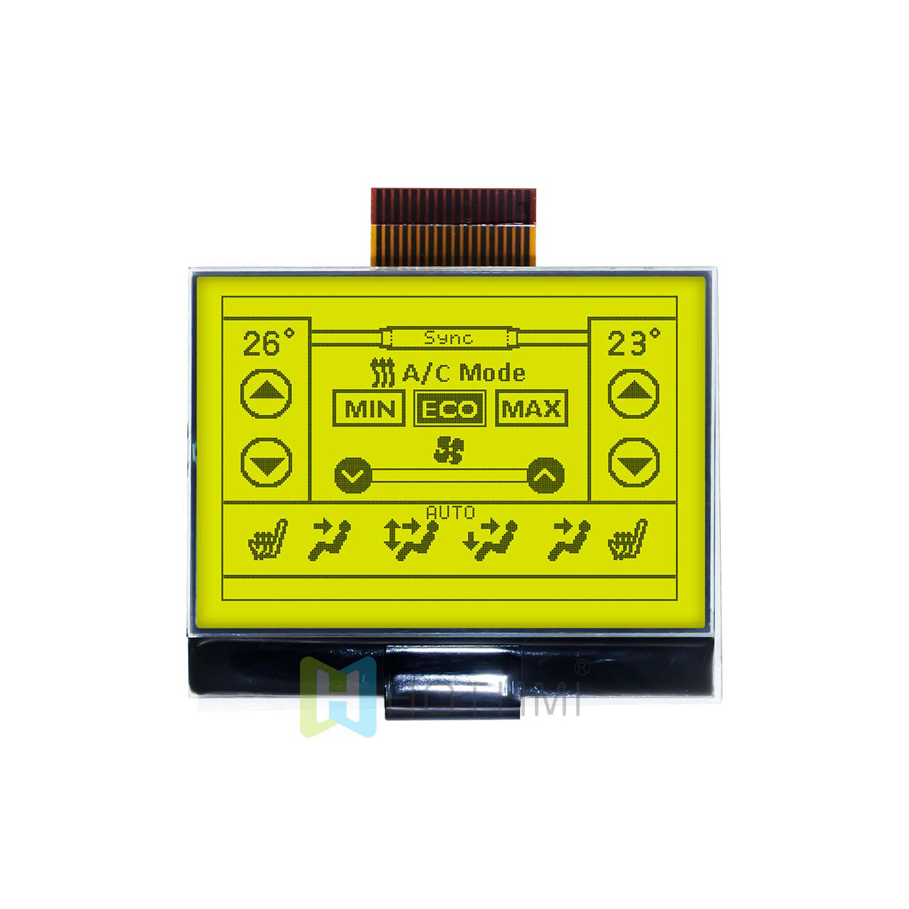
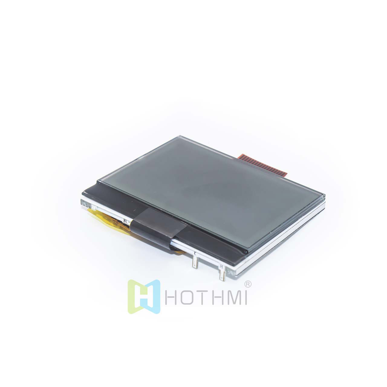
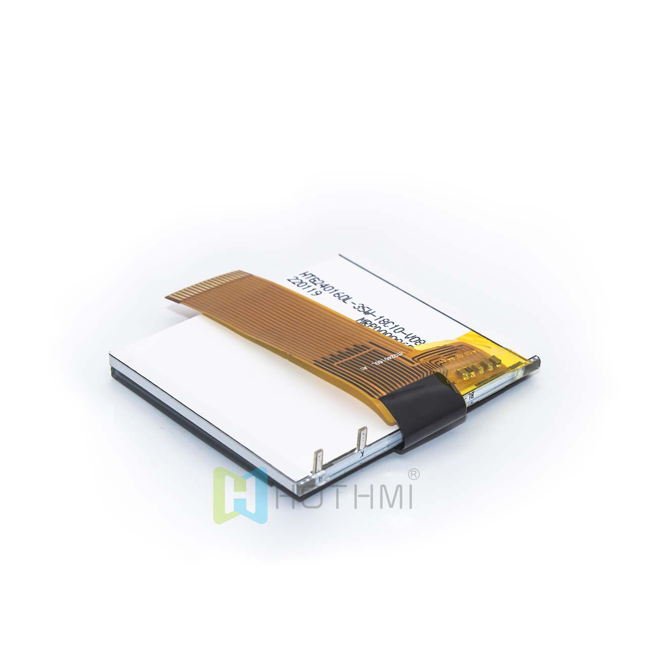
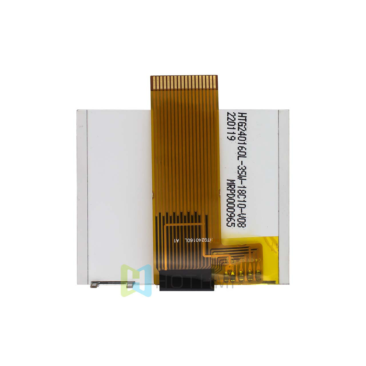
The HTG240160L-31W is a black-and-white dot matrix LCD module adopting advanced COG (Chip-on-Glass) packaging technology. The COG process directly bonds the LCD driver chip to the glass substrate, which greatly reduces the physical size and thickness of the module and significantly improves the reliability of electrical connections.
Core Optical and Driving Parameters
- Resolution: 240 × 160 pixels, supporting high-density graphics and fine display of multi-line text.
- Display Mode: FSTN (Film-compensated Super-twisted Nematic), positive display, transflective. The transflective design combines the advantages of reflective and transmissive types, enabling clear reading by reflecting ambient light under direct strong sunlight, and excellent visibility by turning on the backlight in low-light environments.
- Viewing Angle: 6 o’clock direction (6H).
- Driving Method: 1/160 Duty, 1/12 Bias.
- Backlight Design: Equipped with 3 high-brightness white LEDs connected in parallel/series, providing uniform, soft and high-contrast background illumination.
Mechanical Structure Specifications
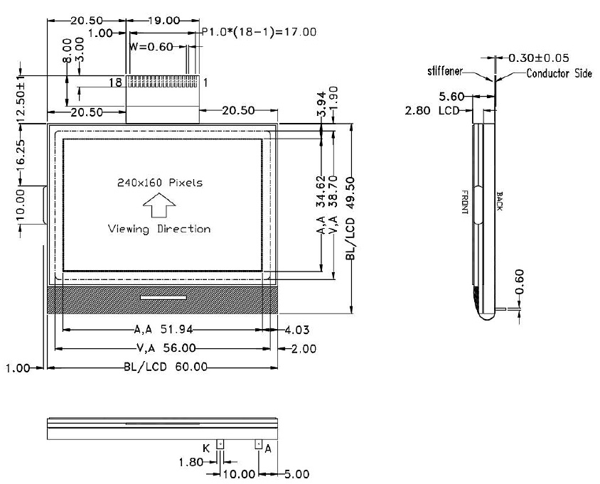
- Outline Dimension: 60.0mm (width) × 49.5mm (height) × 5.6mm (thickness).
- Ultra-thin Design: The overall thickness of only 5.6mm makes it easy to embed into various portable, handheld and compact miniature instruments and meters.
Display COG 240X160 Circuit Diagram Analysis
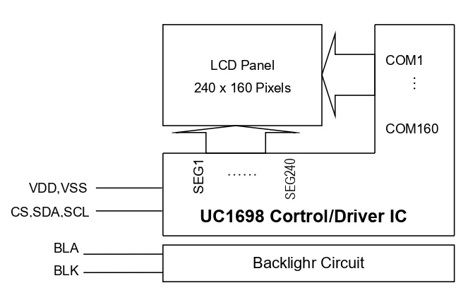
The internal architecture of this Display COG module is highly streamlined, with its core being the integrated high-performance UC1698 control and driver IC. The following is an analysis of the system topology and signal flow of the Display COG module.
Display COG 240X160 Key Node Description of Circuit Architecture
- UC1698 Driver Core: The main MCU writes display data or control commands to the built-in display RAM (GRAM) of UC1698 through a high-bandwidth bus, ensuring stable operation of the Display COG module.
- COM & SEG Driver Output: The UC1698 chip directly outputs 160 row strobe signals (COM1 ~ COM160) and 240 column segment signals (SEG1 ~ SEG240), which precisely control the deflection of liquid crystal molecules in a matrix scanning manner to render fine black-and-white dot matrix images for the Display COG screen.
- Independent Backlight Circuit: The backlight part (BLA, BLK) is physically isolated from the internal logic drive circuit, making it convenient for engineers to adjust the backlight brightness according to product power consumption requirements (e.g., using PWM pulse width modulation technology) for the Display COG display.
Key highlights and differentiating advantages of Display COG 240X160
Among numerous LCD solutions, this Display COG module has become a preferred choice for upgrading industrial equipment with the following differentiated features:
– All-weather High Visibility (FSTN + Transflective): Traditional STN screens are prone to reflection under strong light. Adopting FSTN compensation film technology, this module eliminates color deviation of traditional screens and provides pure black-and-white visual contrast. Combined with transflective characteristics, it ensures clear visibility without dead ends whether outdoors under scorching sun (relying on reflected light) or in dark mines and closed machine rooms (turning on LED backlight).
– Low Power Consumption and High Integration via COG Process: By removing the traditional PCB driver backplane and directly bonding the IC to the glass, it not only reduces material loss but also lowers parasitic capacitance and contact resistance. The overall operating current is extremely small, which can significantly extend the battery life of portable battery-powered devices.
– Simplified 3-wire SPI Serial Interface: Only three standard I/O lines (SDA, SCLK and CS) are required to complete high dynamic screen refresh. This frees up a large amount of hardware resources of the main MCU, enabling low-pin-count microcontrollers (such as Cortex-M0/M3, STM8, ESP32, etc.) to easily drive a 240×160 large dot matrix screen.
– Industrial-grade Design with Wide Voltage and Wide Temperature: The logic power supply supports a wide voltage range of 3.0V ~ 3.3V, enabling stable operation even under battery voltage drop. Its storage temperature ranges from -20°C to +70°C, fully meeting the standards of harsh industrial and outdoor equipment applications.
In-depth FAQ Analysis of Display COG 240X160
Q1: What are the standard timings for software reset and hardware reset during power-on initialization of the module?
A: To ensure that the internal logic circuit of the module is completely cleared and the configuration is loaded correctly, a strict reset and delayed power-on timing must be followed:
- Hardware Reset (controlled by /RES pin): Keep the reset terminal (/RES) at LOW level while the system VDD power supply is turned on and stabilized.
- Hold and Release Delay: According to the official standard reference code, after pulling the hardware reset pin low (RES=0), delay for at least 500ms, then release and pull the reset pin high (RES=1). After pulling high, wait for at least 200ms of stabilization time before allowing the MCU to send the first initialization command.
- Software Reset Command: After the hardware reset is completed, the first control command sent by the MCU should be 0xE2 (Soft Reset), which performs a second soft refresh on the register state machine inside the IC to ensure that subsequent settings (such as bias ratio 0xEB, video memory mapping 0xC0, etc.) are correctly written 100%.
Q2: If the screen response slows down or the text fades when using the module in a low-temperature outdoor environment (e.g., around -10°C), is this a product failure? How to optimize it?
A: This is not a product failure but an inherent physical property of all TN/STN/FSTN liquid crystal materials.
The technical manual clearly states in the “Caution for Operation” section that when the temperature is lower than the lower limit of the normal room temperature operating range, the viscosity of liquid crystal molecules increases, slowing down their deflection speed under an electric field.
Macroscopically, this manifests as a significant delay in screen response time and even ghosting. Conversely, at extremely high temperatures, the entire screen may darken. This phenomenon will completely disappear automatically when the temperature returns to the normal rated operating temperature range, without causing physical damage to the display life or components.
Hardware Optimization Countermeasures
If your product must work outdoors in severe cold at -10°C to -20°C for a long time, it is recommended that:
- Increase the driving voltage in the driver software (dynamically adjust the Vbias bias voltage and contrast value via command 0x81 to enhance the driving force of liquid crystal molecules at low temperatures);
- In product structural design, use the tiny heat generated by the backlight LED for local heat preservation, or attach a miniature low-power PI heating sheet on the back of the LCD screen, and perform closed-loop temperature control with a single-chip microcomputer through a temperature sensor.